background image

5

Application

Free-standing communication ped-
estal made of sect

ional extruded 

alumi

nium, powder coated / 

painted, with base flange. Inclusive 

of mounting frame to accommodate 
functional modules.

Electrical voltage

Mounting, installation and 

servicing 

work on electrical devices may only 
be performed b

y a suitably qualifi

ed 

electrician.

1 Scope of supply

KS/KSF 613/616-…

Pedestal w

ith floor flange

Front panel 

3x screw caps

3x hexagonal scr

ews M 10 x 80

3x plain washers

3x heavy-duty dowels 

16 

x

 60

LS 604/608-…

Pedestal with 

fl

oor 

fl

ange

Front panel

3x screw caps

3x hexagonal screws M

 6 

x

 50

3x plain washers

3x threaded dowels 

12 

x

 50

Mounting

I

nstallation is only possible on 

solid ground such as a concrete 
foundation wi

th “B 25“ concrete 

or pressure-resistant natural stone. 
Foun

dation size 500 x 500 x 700 

mm or ground

 slab of approx. 1 m² 

and 150 mm thick.

For the light pedestal LS

 60

4

/608

-


a smaller foundation is suf

fi

cient. 

For 

fix

ture in loose soil

,

 ground spike 

ZES

/

LS

 611

-

 is available as an 

accessory.

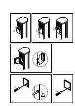
Remove the front panel

Mark the position of the fastening 

holes and drill.

KS/K

SF 613/616-…

16 

mm dia. appr. 

60 

mm deep

LS 604/608-…

mm dia. appr. 

60 

mm deep

I

nsert the dowels

,

 guide the con-

necting cable through the 

fl

oor plate 

English

and fasten the pedestal. Position the 
screw cap.

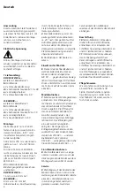
Remove combination terminal 

strip from the module packaging, 
centre it turned around 

45°

 to the 

left on the retaining plate and latch 
into position by rotating it around 
a quarter turn in the clockwise 
direction so that the terminal desig-
nations can be read vertically posi-
tioned one above the other.

Insert the front panel on the 

column.

Inserting the 

m

o

d

ules

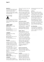
Connect the plug of the ribbon 

cable to the combination terminal 
strip. Applying a light pressure, 
underpin the module in the module 
slot of the MR

 611

-

 opposite the 

movable locking bolt. Exerting a 
slightly higher degree of pressure, 
clip into place on the other side.

Mo

d

ule re

m

oval

Remove the module from the 

mounting frame: The unlocking 
mechanism is actuated by pressing 
in the Vario key, applying light pres-
sure. The opening for the Vario key 
is located between two modules. 
The Vario key is supplied together 
with the mounting frame. Unlocking 
releases one or two modules simul-
taneously. Access to the unlocking 
mechanism can be additionally 
secured using the pilfer safeguard 
accessory ZDS

 601

-

 and the pilfer 

safeguard controller DSC

 602

-


(

see product information  

ZDS

 601

-

…)

.

Re

m

ove the front panel

The front panel can only be 

removed if the directly adjacent 
module has 

fi

rst been removed from 

the mounting frame.

Servicing

Release the wire bracket on the 

back of the module and lock into 
position into the retainer on the 
combination terminal strip. This 
allows the modules to be function 
tested and measured through. After 
completion of servicing, suspend the 

retaining bracket back onto the back 
of the module.

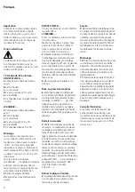
Lettering

10 

Open the call button module 

using a screwdriver and remove the 
inscription panel. To insert, underpin 
the inscription panel on one side and 
close by exerting a light pressure.

11 

Remove the information module 

by levering open the catch on one 
side at the edge and removing 
the inscription panel. To insert the 
inscription panel again, underpin 
on one side and close by exerting a 
light pressure. The inscription inserts 
made of special water-repellant 
paper can be reordered as required.

Care instructions

To retain the optimum appearance 
of the Siedle door loudspeaker

,

 we 

recommend regular cleaning using a 
mild soap

,

 followed by rubbing dry 

with a soft cloth.

Summary of Contents for KS 613 Series

Page 1: ...duit Colonne de communication Colonne lumineuse Opuscolo informativo sul prodotto Stele di comunicazione Stele di illuminazione Productinformatie Communicatiezuile Lichtzuil Produktinformation Kommunikationsstander Belysningsstander Produktinformation Kommunikationspelare Ljuspelare KSF 613 KSF 616 KS 613 KS 616 LS 604 LS 608 ...

Page 2: ...2 a b c d e f 1 4 2 5 8 3 ...

Page 3: ...3 6 7 9 10 11 ...

Page 4: ...tärke Für die Licht Stele LS 604 608 reicht ein kleineres Fundament Für die Befestigung im losen Erdreich gibt es als Zubehör den Erdspieß ZES LS 611 2 Frontblende abnehmen 3 Befestigungslöcher anzeichnen und bohren KS KSF 613 616 16 mm ø ca 60 mm tief LS 604 608 8 mm ø ca 60 mm tief Dübel einsetzen Anschlussleitung durch die Bodenpatte führen und Stele befestigen Schraubenab deckung aufsetzen 4 K...

Page 5: ...nnect the plug of the ribbon cable to the combination terminal strip Applying a light pressure underpin the module in the module slot of the MR 611 opposite the movable locking bolt Exerting a slightly higher degree of pressure clip into place on the other side Module removal 7 Remove the module from the mounting frame The unlocking mechanism is actuated by pressing in the Vario key applying light...

Page 6: ...le sur la colonne Mise en place des modules 6 Branchez la prise du câble plat sur le bornier combiné Encastrer le module dans l emplacement pour modules du MR 611 du côté opposé au verrou de fermeture mobile et en exerçant une légère pression et l encliqueter de l autre côté en augmentant quelque peu la pression Retrait du module 7 Retirer les modules du cadre de montage le mécanisme de déver roui...

Page 7: ...nne Installazione dei moduli 6 Inserire la spina del cavo piatto nella morsettiera Spingere il modulo nel posto moduli del MR 611 di fronte alla serratura in materiale sin tetico rosso esercitando una leggera pressione e premendo leggermente più forte sull altro lato farlo inne stare Rimozione del modulo 7 Rimuovere i moduli dal telaio di montaggio Il meccanismo di sbloc caggio viene attivato inse...

Page 8: ...r de beweeglijke sluitgrendel onder lichte druk onderin vast en klik hem met iets meer druk aan de andere zijde vast Module ontname 7 Module uit het montageframe verwijderen Het ontgrendelingsme chanisme wordt door het plaatsen van de variosleutel met lichte druk losgemaakt De opening voor de variosleutel bevindt zich tussen twee modules De variosleutel is meege leverd met het montageframe Het ont...

Page 9: ...ret over hinanden 5 Frontpanelet sættes på søjlen Installation af moduler 6 Fladbåndskabelstikket føres ind i klemrækken Modulet klemmes ind på modulpladsen i MR 611 over for den bevægelige låseflig med et let tryk og klikkes med et noget kraf tigere tryk på plads i den anden side Udtagning af modulet 7 Tag moduler ud af montage rammen Oplåsningsmekanismen udløses ved at stikke varionøglen i med e...

Page 10: ... Sätt fast fronttäckskyddet på pelaren Isättning av modulerna 6 Placera bandkabelns stickpropp på kombikopplingsplinten Kläm ner modulen i modulplatsen på MR 611 mittemot den rörliga låsregeln med lätt tryck och snäpp fast den på andra sidan med litet mer tryck Modulupptagning 7 Ta ur modulerna ur monterings ramen Upplåsningsmekanismen utlöses genom att sticka in Vario nyckeln med ett lätt tryck Ö...

Page 11: ...11 ...

Page 12: ...unentgeltlich an Erfassungs stellen öffentlich rechtlicher Entsorgungsträger z B auf Wertstoff bzw Recyclinghöfen abgeben Besitzer von Altgeräten können diese unter den Voraussetzungen des 17 Absatz 1 und 2 ElektroG auch bei den dort genannten rück nahmepflichtigen Vertreibern unent geltlich abgeben Vor der Abgabe an einer Erfassungs stelle sind Altbatterien und Altakku mulatoren die nicht vom Alt...

Reviews: