5136-DNP-PCI
Hardware Reference
© 1999 SST/Woodhead Canada Limited
8
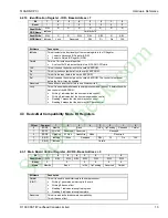
4.2.4 Memory Configuration Register 0 - MCR0
Bank Selection
Bit
7
6
5
4
3
2
1
0
Read/Write
R
R
R
R
R/W
R/W
R/W
R/W
Reset
0
0
Name
Reserved
Bank
Bit Name
Description
Bank
The 5136-DNP-PCI has 256k of memory accessible to the host. These bits select
which bank of memory the host can access.
•
In 16k mode the bank number may be 0 through 15 (or 0x0 - 0xF)
•
In 32k mode the bank number may be 0 through 7.
The primary host interface window is located in bank 0.
Note that by setting the Bank to 0 and the Bank Size to 16K, all banks can be linearly
accessed in the 256K window, Bank 0 being mapped to the lowest 16K through to
Bank 15 mapped to the highest 16K.See section 4.2.5.
Reserved
These bits are reserved for future expansion.
Always write 00 to these bits.
4.2.5 Memory Bank Selection
Pro Mode
Pro Mode
Compatible
Mode
Compatible
Mode
Comment*
16k Bank Size
32k Bank Size
16k Bank Size
32k Bank Size
0
0
3
0
Host Interface
1
0
2
0
2
1
1
1
3
1
0
1
4
2
N/A
2
5
2
N/A
2
6
3
N/A
3
7
3
N/A
3
8
4
N/A
4
9
4
N/A
4
10
5
N/A
5
11
5
N/A
5
12
6
4
6
13
6
5
6
Module Load
14
7
6
7
Region
15
7
7
7
*The shaded area is reserved for future use
4.2.6 Memory Configuration Register 1 - MCR1
Memory Mode
Bit
7
6
5
4
3
2
1
0
Read/Write
R
R
R
R/W
R
R
R
R
Reset
0
0
0
1
0
Name
AddrMode
Win32K
Reserved
Bit Name
Description
StockCheck.com


