Overview
11
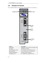
2.2.1 LEDs
There are two LEDs on the scanner, the SYS LED and the COMM LED.
The SYS LED indicates overall status of scanner operations.
The COMM LED indicates communication status.
Refer to section 4.3, Status LEDs, in this manual for more detailed
information.
2.2.2 9-pin ProfiBus connector
The 9-pin ProfiBus connector connects the scanner to the ProfiBus network.
2.2.3 Configuration port
Use the configuration port to upload I/O configurations exported from the
SST ProfiBus Configuration Tool or Siemens COM PROFIBUS to the
scanner.
Summary of Contents for SST-PFB-SLC
Page 7: ...Contents vii Technical Data 105 Index 107 A...
Page 8: ...SST PFB SLC User s Guide viii...
Page 14: ...SST PFB SLC User s Guide 6...
Page 20: ...SST PFB SLC User s Guide 12...
Page 34: ...SST PFB SLC User s Guide 26...
Page 53: ...45 6 DP Master Application Examples...
Page 56: ...SST PFB SLC User s Guide 48 Sample Program...
Page 57: ...DP Master Application Examples 49 Sample continued...
Page 66: ...Using the Scanner Module as a DP Slave 58...
Page 67: ...59 8 Using FDL...
Page 75: ...Using FDL 67 Sample Program...
Page 76: ...SST PFB SLC User s Guide 68 Sample Continued...
Page 80: ...SST PFB SLC User s Guide 72 Sample Program...
Page 81: ...SST PFB SLC User s Guide 73 Sample Continued...
Page 85: ...SST PFB SLC User s Guide 77...
Page 86: ...SST PFB SLC User s Guide 78...
Page 87: ...79 9 Diagnostics This chapter describes system diagnostics...
Page 105: ...97 11 Network Parameter Defaults This chapter describes network defaults...


