SST-PFB-SLC User’s Guide
52
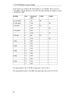
In the following example, the first module is a 1794-IB16, the second is a
1794-OB16, and the third is a 1794-IE8. The SST-PFB-SLC scanner is in slot
2 of the SLC rack.
The input data for the 1794-IB16 maps into I:2/0 to I:2/15.
The output data for the 1794-OB16 module maps into O:2/16 to O:2/31.
Module
Slot
Assigned
type
I Addr
O Addr
pre-assigned
0
1AI
Q0
-
pre-assigned
1
1AO
-
Q2
1794-IB16
2
1AI
P0
-
3
1AO
-
Q4
1794-OB16
4
000
-
-
5
1AO
-
P2
1794-IE8
6
9AI
P4
-
7
1AO
-
Q6
empty
8
000
-
-
9
000
-
-
empty
10
000
-
-
11
000
-
-
empty
12
000
-
-
13
000
-
-
empty
14
000
-
-
15
000
-
-
empty
16
000
-
-
17
000
-
-
Summary of Contents for SST-PFB-SLC
Page 7: ...Contents vii Technical Data 105 Index 107 A...
Page 8: ...SST PFB SLC User s Guide viii...
Page 14: ...SST PFB SLC User s Guide 6...
Page 20: ...SST PFB SLC User s Guide 12...
Page 34: ...SST PFB SLC User s Guide 26...
Page 53: ...45 6 DP Master Application Examples...
Page 56: ...SST PFB SLC User s Guide 48 Sample Program...
Page 57: ...DP Master Application Examples 49 Sample continued...
Page 66: ...Using the Scanner Module as a DP Slave 58...
Page 67: ...59 8 Using FDL...
Page 75: ...Using FDL 67 Sample Program...
Page 76: ...SST PFB SLC User s Guide 68 Sample Continued...
Page 80: ...SST PFB SLC User s Guide 72 Sample Program...
Page 81: ...SST PFB SLC User s Guide 73 Sample Continued...
Page 85: ...SST PFB SLC User s Guide 77...
Page 86: ...SST PFB SLC User s Guide 78...
Page 87: ...79 9 Diagnostics This chapter describes system diagnostics...
Page 105: ...97 11 Network Parameter Defaults This chapter describes network defaults...


