17
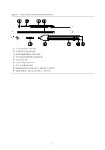
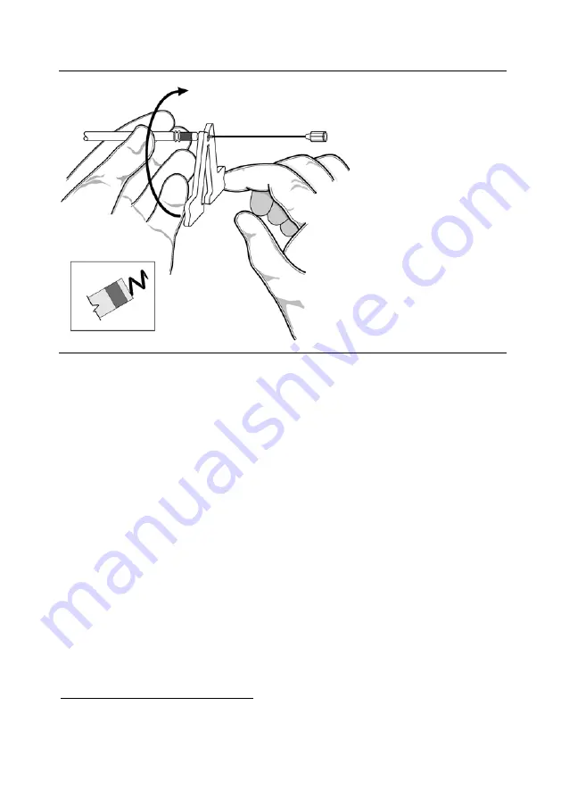
Figure 7. Using the clip-on tool
4.
While keeping the lead as straight as possible, grasp the connector boot with one hand and
with the other hand, rotate the clip-on tool clockwise to extend the helix. (Refer to the
Technical Specifications tables for the number of rotations required to extend the helix.) The
helix is fully extended when at least 2 turns are visible beyond the lead tip.
CAUTION
While extending or retracting the helix:
Keep the lead as straight as possible. Bending or kinking the lead body may
interfere with the helix movement or cause damage to the lead.
Do not grasp the lead body. Doing so may interfere with the helix movement or
cause damage to the lead.
5.
Rotate the clip-on tool counter-clockwise to retract the helix.
CAUTION
Do not further rotate the connector pin after the helix is fully extended or
retracted. Doing so may damage the helix mechanism.
6.
To remove the clip-on tool, pinch the handles and withdraw the connector pin from the tool.
Selecting and Opening a Vein
The suggested entry site is the left cephalic vein entered through a venous cutdown. Alternatively,
the lead may be implanted percutaneously through the left subclavian vein. However, studies
indicate that the incidence of lead damage may be decreased with the lead placed by cephalic
9
Magney, J.E., Flynn, D. M., Parsons, J.A., et al.: Anatomical Mechanisms Explaining Damage to Pacemaker Leads, Defibrillator
Leads, and Failure of Central Venous Catheters Adjacent to the Sternoclavicular Joint. PACE 16 (I): 445-457, 1993.Jacobs, D.M.,
Fink, A.S., Miller, R.P., et al.: Anatomical and Morphological Evaluation of Pacemaker Lead Compression. PACE 16 (I): 434-444,
1993.


