background image


18 


vein cutdown or, if a percutaneous subclavian entry is chosen, with a puncture site as lateral as 
possible (in the area under the lateral two-thirds of the clavicle, lateral to the subclavius muscle). 
The right subclavian vein and the internal jugular vein can also be used. 

Inserting the Lead 

A vein pick is included in the package to aid in inserting the lead into the vein. Its use is optional 
and depends on the implantation technique chosen. 
To use the vein pick: 

1.


Isolate and open the selected vein with scissors or a scalpel. 

2.


Orient the point of the vein pick in the direction the lead will be passed and insert the point 

through the incision into the vessel lumen. 

3.


Raise and tilt the vein pick gently, and pass the lead tip under the pick into the vein lumen. 

CAUTION 
Do not use the vein pick for puncturing the vein, dissecting tissue during 
cutdown, or manipulating the lead. 

Positioning the Active Fixation Lead 

Confirm that the helix is completely retracted before implantation. When the helix is completely 
retracted, the helix tip might extend slightly beyond the lead tip. 

Note


If blood clogs the helix, repositioning may require a greater number of pin rotations to 
extend the helix. Repeated repositioning attempts may impair the helix extension 
mechanism. 

1.


Under fluoroscopic guidance and with the helix retracted, advance the lead into the right 

atrium. 

2.


To aid in passing the lead through the tricuspid valve and into the right ventricle: 

-


remove the stylet from the lead 

-


shape the distal end of the stylet into a gentle curve 

-


carefully reinsert the stylet into the lead 

The flexibility of the lead's distal defibrillation coil allows the distal end of the lead to conform 

to the shape of the stylet. 

CAUTION


To avoid damage to the stylet and lead, do not attempt to curve the stylet while it 
is inserted in the lead. Do not use a sharp object to curve the distal end of the 
stylet. 

3.


Under close fluoroscopic monitoring, advance the curved lead/stylet through the tricuspid 
valve and into the ventricular chamber. 

4.


Pull the stylet back a few centimeters to reduce the risk of the lead damaging the valves or 
penetrating the heart muscle when it continues down into the ventricle. 

5.


Continue to advance the lead. When the tip reaches position in the right ventricle, retract the 
stylet an additional ten centimeters or more. 
Accurate electrode positioning is vital for stable sensing and pacing. Verify that the lead tip is 

Summary of Contents for Optisure LDA210

Page 1: ...DA210 LDA220Q LDA230Q LDA210Q LDP220 LDP230 LDP220Q LDP230Q Quadpole connector IS 1 and DF 1 connector Active fixation Passive fixation True bipolar Dual coil Single coil Steroid eluting Endocardial Defibrillation leads User s Manual ...

Page 2: ...cer and birth defects or other reproductive harm For more information go to www P65Warnings ca gov Unless otherwise noted indicates that the name is a trademark of or licensed to St Jude Medical or one of its subsidiaries ST JUDE MEDICAL and the nine squares symbol are trademarks and service marks of St Jude Medical LLC and its related companies Pat http patents sjm com 2017 St Jude Medical LLC Al...

Page 3: ...220 LDP230 LDP220Q and LDP230Q are quadripolar leads Models LDA210 and LDA210Q are tripolar leads Portions of the lead body have an Optim silicone polyurethane copolymer insulation overlay The lead body insulation tubing is Optim insulation and silicone rubber for long term biocompatibility and biostability The lead body is treated with Fast Pass coating to provide lubricity during lead implant Af...

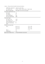
Page 4: ...im ETFE and PTFE Defibrillation electrodes platinum iridium alloy Pacing electrode helix titanium nitride coated platinum iridium alloy Steroid eluting plug DSP Electrode surface area mm2 Pacing tip 6 Pacing ring 17 Distal defibrillation 367 Proximal defibrillation 638 638 n a 638 638 n a Electrode length Pacing tip mm 1 80 Pacing ring mm 2 79 Distal defibrillation cm 5 Proximal defibrillation cm ...

Page 5: ...g Tip to ring electrode mm 11 Tip to distal defibrillation electrode mm 17 Tip to proximal defibrillation electrode cm 17 21 17 21 Connector type3 Sense pace 1 IS 1 bipolar 3 2 mm connector n a Defibrillation 2 DF 1 unipolar 3 2 mm connectors n a Sense pace defibrillation n a DF4 LLHH Materials4 Body Fast Pass Conductors 35N LT and 35N LT DFT Connectors MPS35N and stainless steel MPS35N Insulators...

Page 6: ... sodium phosphate Electrode surface area mm2 Pacing tip 3 5 Pacing ring 17 Distal defibrillation 367 Proximal defibrillation 638 Electrode length Pacing tip mm 0 45 Pacing ring mm 2 41 Distal defibrillation cm 5 Proximal defibrillation cm 8 Electrical resistance Ω Pace 60 cm 33 65 cm 36 75 cm 42 52 cm 29 58 cm 32 65 cm 36 Sense 15 6 Defibrillation 6 Maximum diameter mm 2 54 at defibrillation elect...

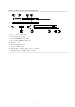
Page 7: ...lectrode cathode 2 Ring electrode anode 3 Distal defibrillation electrode 4 Proximal defibrillation electrode 5 Suture sleeve 6 Lead body trifurcation 7 IS 1 connector boot 8 Sense pace connector IS 1 bipolar 3 2 mm 9 Defibrillation connectors DF 1 3 2 mm ...

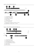
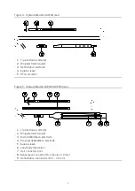
Page 8: ...ve 5 Lead body trifurcation 6 IS 1 connector boot 7 Sense pace connector IS 1 bipolar 3 2 mm 8 Defibrillation connector DF 1 3 2 mm Figure 3 Optisure Models LDA220Q LDA230Q lead 1 Tip electrode cathode 2 Ring electrode anode 3 Distal defibrillation electrode 4 Proximal defibrillation electrode 5 Suture sleeve 6 DF4 connector ...

Page 9: ...eve 5 DF4 connector Figure 5 Optisure Models LDP220 LDP230 lead 1 Tip electrode cathode 2 Ring electrode anode 3 Distal defibrillation electrode 4 Proximal defibrillation electrode 5 Suture sleeve 6 Lead body trifurcation 7 IS 1 connector boot 8 Sense pace connector IS 1 bipolar 3 2 mm 9 Defibrillation connectors DF 1 3 2 mm ...

Page 10: ...tients with tricuspid valvular disease or a mechanical tricuspid valve Patients with ventricular tachyarrhythmias resulting from transient or correctable factors such as drug toxicity electrolyte imbalance or acute myocardial infarction Patients for whom a single dose of 1 0 mg of dexamethasone sodium phosphate is contraindicated For use with extra firm red color knob stylets models LDA220 LDA230 ...

Page 11: ...revent potential malfunction of the lead Use only St Jude Medical suture sleeves to immobilize and protect the lead against damage from ligatures Do not place the lead near another implanted lead to ensure sensing and defibrillation efficacy Do not rotate the connector pin after the helix is fully extended or retracted as doing so may damage the lead To avoid distortion of the Optisure lead tip do...

Page 12: ... invasive intervention to treat or resolve Observations are those clinical events with potential adverse effects that do not require invasive intervention A total of 55 complications were reported in 50 patients and 30 observations were reported in 29 patients The RV lead or DF4 connector related complication rate at 30 months for Durata 7120Q 7121Q 7122Q and 7170Q leads was 2 9 Table 4 Observed A...

Page 13: ...ing possibly resulting in nondetection of arrhythmia oversensing of artifact possibly causing inappropriate delivery of therapy from the pulse generator intermittent or continuous loss of defibrillation cardioversion or pacing therapy possible muscle or nerve stimulation in the pocket area intermittent or continuous loss of cardioversion defibrillation therapy sensing or pacing therapies Cardiac p...

Page 14: ... study SJ4 Post Approval Study The purpose of the clinical study which included Durata 7120Q 7121Q 7122Q and 7170Q lead models was to evaluate the safety and effectiveness of the SJ4 system device with DF4 connector and RV high voltage SJ4 leads SJ4 is equivalent to DF4 The Q version of the Durata lead models are identical to the non Q version except for the type of connector Patients Studied As o...

Page 15: ...onths as of the interim report are summarized in the following table Table 7 Summary of pace sense measurements at implant and follow up visits up to 36 months Visit Type RV Lead Capture Threshold 0 5 ms Pulse Width RV Lead Pacing Impedance R wave Amplitude8 IMPLANT Mean SD Range n 1689 0 60 0 28 V 0 25 to 5 00 V n 1697 566 137 Ω 230 to 1600 Ω n 1625 9 8 2 6 mV 0 5 to 12 0 mV 6 month Mean SD Range...

Page 16: ...aging external defibrillation and measuring lead signals should be available for immediate use during lead implantation and tachyarrhythmia induction testing Additional quantities of all sterile implantable devices should be available in case of accidental contamination or damage Package Inspection St Jude Medical packages all leads under clean conditions and sterilizes them using ethylene oxide g...

Page 17: ... pressure to the tips of electrodes Avoid contact of the electrode with a hard surface and guard against contaminating the lead tip with insulating materials such as lubricants or medical adhesive Use powderless surgical gloves when handling the lead or remove talc from surgical gloves before handling the lead Because lead insulation attracts particulate matter such as lint and dust minimize conta...

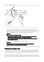
Page 18: ...ving a stylet hold the lead at the connector end with the lead straight to avoid stress on the lead body Stylet Guide Funnel IS 1 models only Use the stylet guide funnel to assist the insertion of a stylet into the lead s IS 1 connector pin Insert the stylet guide over the IS 1 connector pin prior to introducing the stylet Preparing the Active Fixation Lead Test the extension and retraction of the...

Page 19: ...ise to retract the helix CAUTION Do not further rotate the connector pin after the helix is fully extended or retracted Doing so may damage the helix mechanism 6 To remove the clip on tool pinch the handles and withdraw the connector pin from the tool Selecting and Opening a Vein The suggested entry site is the left cephalic vein entered through a venous cutdown Alternatively the lead may be impla...

Page 20: ...epositioning may require a greater number of pin rotations to extend the helix Repeated repositioning attempts may impair the helix extension mechanism 1 Under fluoroscopic guidance and with the helix retracted advance the lead into the right atrium 2 To aid in passing the lead through the tricuspid valve and into the right ventricle remove the stylet from the lead shape the distal end of the styl...

Page 21: ... the other hand rotate the clip on tool clockwise to extend the helix Refer to the Technical Specifications sheet for the number of rotations required to extend the helix When viewed on the fluoroscope the helix is fully extended when at least 2 turns are visible beyond the lead tip Figure 8 Figure 8 Extension and retraction of the helix 1 Helix fully extended 2 Helix fully retracted 3 Marker ring...

Page 22: ...y reinsert the stylet into the lead The flexibility of the lead s distal defibrillation coil allows the distal end of the lead to conform to the shape of the stylet CAUTION To avoid damage to the stylet and lead do not attempt to curve the stylet while it is inserted in the lead Do not use a sharp object to curve the distal end of the stylet 3 Under close fluoroscopic monitoring advance the curved...

Page 23: ...asuring the sensed R wave amplitude and determining the pacing threshold Refer to the appropriate pulse generator manual for recommended procedures and acceptable values Note For DF4 leads use a sterile patient cable with a plunger clip such as Models 4160 or 4161 or the IS4 DF4 Connector Sleeve Model EX3151 The use of alligator clips directly on the lead is not recommended because they may damage...

Page 24: ...ents however no lead configuration may provide reliable defibrillation and the use of an alternative lead system should be considered CAUTION If a thoracotomy is required it should be done during a separate procedure After successful defibrillation testing suture the lead in place and connect it to the pulse generator Suturing the Lead After verifying acceptable lead performance use the suture sle...

Page 25: ...result in damage to the lead If an accessory suture sleeve is utilized 1 Carefully open the slit in the sleeve and position the sleeve on the lead body 2 Follow the procedure above to suture and secure the sleeve Connecting the Lead to the Pulse Generator CAUTION To prevent damage to the lead do not use excessive force on the lead body or connectors To avoid dislodgement or potential fracture do n...

Page 26: ...enerator placement can cause damage affecting the long term reliability of the connector and can impair its function 5 After connecting the lead to the pulse generator test the function of the lead with the pulse generator to ensure sensing pacing and cardioversion defibrillation efficacy Post Implantation Follow Up St Jude Medical strongly recommends pre discharge and chronic follow up electrophy...

Page 27: ...ilable for use with the products described in this manual Clip on tool active fixation models only DF 1 plug single coil model only Lead cap Stylets Stylet guide funnel IS 1 models only Suture sleeve Vein pick IS4 DF4 connector sleeve Stylet Color Codes Table 9 Stylet color codes Knob Color Description Diameter Light green Extra soft straight 40 mm taper 0 014 in 0 36 mm Green Soft straight 20 mm ...

Page 28: ......

Page 29: ......

Page 30: ...agement Division 15900 Valley View Court Sylmar CA 91342 USA 1 818 362 6822 St Jude Medical Coordination Center BVBA The Corporate Village Da Vincilaan 11 Box F1 1935 Zaventem Belgium 32 2 774 68 11 sjm com August 2017 ARTEN100158802 B ...

Reviews: