background image


41 


The radio receiver  in the device is using the same frequency and bandwidth as the transmitter. 


Cables and transducers: 
Cables and transducers are not used during normal  use of the device nor while programming  the 
device. 

Quality of Service for Wireless Technology 

Bluetooth

®

 Smart wireless  technology enables communication between the generator and the clinician 

programmer or patient controller. The requirements for the quality of service (QoS) vary depending on 
the use environment (operating room, recovery  room, and home environment). 
After the clinician programmer or patient controller is paired with a generator, the Bluetooth wireless 
technology symbol  is  visible on the clinician programmer  or patient controller in the upper right-hand 
corner of the screen. When the Bluetooth Smart wireless  technology connection is not active, the 
symbol  appears dimmed. 
Other requirements include a semi-duplex transmission  with a required acknowledge, a transmission 
latency in each direction (2x), and a receive-to-transmit  mode (RX-to-TX) time. Data is resent if not sent 

Summary of Contents for Proclaim DRG 3664

Page 1: ...Proclaim DRG Implantable Pulse Generator Model 3664 Clinician s Manual ...

Page 2: ...ark of or licensed to St Jude Medical orone of its subsidiaries ST JUDE MEDICAL and the nine squares symbol are trademarks and service marks of St Jude Medical LLC and its related companies Pat http patents sjm com 2017 St Jude Medical LLC All Rights Reserved ...

Page 3: ...ations 1 MRI Safety Information 2 Warnings 2 Precautions 8 Adverse Effects 14 System Overview 16 Product Description 18 Package Contents 19 Identifying the IPG 19 Directions for Use 20 Creating an IPG Pocket 21 Connecting a Lead or Extension to the IPG 22 Implanting the IPG 26 Replacing the IPG 28 ...

Page 4: ...sories 34 IPGs 34 Programmers and Controllers 34 Leads and Extensions 35 Trial System 36 Appendix C Regulatory Statements 36 Disposal Guidelines for Battery Powered Devices 36 Statement of FCC Compliance 37 Statement of Compliance With License Exempt RSS Standard Canada 38 Identification Information for Product Registration 38 Wireless Technology Information 39 Radio Transmitter Cables Transducers...

Page 5: ...iii Appendix D Symbols and Definitions 43 Additional Symbols for Product Labels 47 Appendix E CE Mark Date 48 ...

Page 6: ......

Page 7: ...rical impulses to nerve structures The system is intended to be used with leads and associated extensions that are compatible with the system Indications for Use This neurostimulation system is indicated for the management of chronic intractable pain Contraindications This system is contraindicated for patients who are Unable to operate the system Poor surgical risks Pregnant Under the age of 18 ...

Page 8: ...tion about MR Conditional products visit the St Jude Medical product information page at sjmprofessional com MRI Warnings The following warnings apply to this neurostimulation system Pregnancy and nursing Safety and effectiveness of neurostimulation for use during pregnancy and nursing have not been established Pediatric use The safety and effectiveness of neurostimulation for pediatric use have n...

Page 9: ... therapy Do not use short wave diathermy microwave diathermy or therapeutic ultrasound diathermy all now referred to as diathermy on patients implanted with a neurostimulation system Energy from diathermy can be transferred through the implanted system and cause tissue damage at the location of the implanted electrodes resulting in severe injury or death Diathermy is further prohibited because it ...

Page 10: ...rm that the neurostimulation system is functioning correctly during the implant procedure and before closing the neurostimulator pocket Implanted cardiac systems Physicians need to be aware of the risk and possible interaction between a neurostimulation system and an implanted cardiac system such as a pacemaker or defibrillator Electrical pulses from a neurostimulation system may interact with the...

Page 11: ...apeutic magnets diagnostic X rays and high output ultrasonic lithotripsy These procedures may cause interference that can affect the operation of the neurostimulator or damage components of the system causing patient harm If patients with a neurostimulator receive any medical treatment in which an electrical current is passed through their body from an external source either the device should firs...

Page 12: ...ure or possible infection Lead movement Patients should be instructed to avoid bending twisting stretching and lifting objects over 2 kg 5 lb for at least six weeks after implantation These activities may cause lead movement resulting in understimulation or overstimulation for the patient Excessive lead migration may require reoperation to replace the leads Scuba diving and hyperbaric chambers Ins...

Page 13: ...rproof Keep them dry to avoid damage Advise patients to not use their device when engaging in activities that might cause it to get wet such as swimming or bathing Device components The use of components not approved for use by St Jude Medical with this system may result in damage to the system and increased risk to the patient Device modification The equipment is not serviceable by the customer T...

Page 14: ...anted Precautions The following precautions apply to this neurostimulation system General Precautions Clinician training Implanting physicians should be experienced in the diagnosis and treatment of chronic pain syndromes and have undergone surgical and device implantation training Patient selection It is extremely important to select patients appropriately for neurostimulation Thorough psychiatri...

Page 15: ...n changing positions or moving However some patients may experience a decrease or increase in the perceived level of stimulation Perception of higher levels of stimulation has been described by some patients as uncomfortable painful or jolting Advise patients who experience these types of stimulation changes to turn down the amplitude or turn off the IPG before making extreme posture changes or ab...

Page 16: ...damage do not use the device as it may be compromised and could cause harm to the patient Return any suspect components to St Jude Medical for evaluation Handle the device with care The clinician programmer and patient controller are sensitive electronic devices that can be damaged by rough handling such as dropping them on the ground Lead inspection Carefully inspect the lead in the sterile field...

Page 17: ... the lead only when satisfied with lead placement If the stylet is removed from the lead it may be difficult to reinsert it Sheath insertion precaution Do not insert the sheath into the epidural space without the lead or guidewire inserted as this may cause injury to the dura The standard implant lead cannot be loaded into the sheath after the sheath is in the body The SlimTip lead however can be ...

Page 18: ...osing the neurostimulator pocket and before the patient leaves the surgery suite Component disposal Return all explanted components to St Jude Medical for safe disposal Hospital and Medical Environments High output ultrasonics and lithotripsy The use of high output devices such as an electrohydraulic lithotriptor may cause damage to the electronic circuitry of an implanted IPG If lithotripsy must ...

Page 19: ...f Bluetooth SIG Inc Security antitheft and radiofrequency identification RFID devices Some antitheft devices such as those used at entrances or exits of department stores libraries and other public places and airport security screening devices may affect stimulation Additionally RFID devices which are often used to read identification badges as well as some tag deactivation devices such as those u...

Page 20: ...cluding involuntary movement caused by stimulation at high outputs if either occurs turn off your IPG immediately Undesirable changes in stimulation which may be related to cellular changes in tissue around the electrodes changes in electrode position loose electrical connections or lead failure or breakage Stimulation in unwanted places such as stimulation of the chest wall Lead migration causing...

Page 21: ...jurious stimulus to the skin or an exaggerated sense of pain Additional risks to the patients as a result of the placement and stimulation of the lead in the area of the dorsal root ganglion DRG include pain from setting the stimulation parameters too high This may occur once the lead is in place and is connected to the neurostimulator and activated The neurostimulator is controlled by a trained o...

Page 22: ...programmer Patient controller Patient magnet The IPG delivers electrical pulses through the leads to electrodes near selected nerve fibers in order to provide therapeutic stimulation The patient magnet can turn the IPG on and off if the physician enabled this functionality Physicians use the clinician programmer to create and modify programs for a patient Patients use the patient controller to con...

Page 23: ...e following image shows how the major system components are intended to interact Figure 1 Interaction among main system components 1 Clinician programmer or patient controller 2 IPG 3 Leads 4 Patient magnet ...

Page 24: ... to a single anatomical area or to multiple areas The IPG communicates wirelessly with system programmers and controllers The IPG can receive software upgrades after implantation to provide patients with additional features as approved by the respective regulatory agencies To upgrade features on the IPG a system programmer is needed For more information about IPG features and specifications see th...

Page 25: ... can view with standard X ray procedures The tag which is located in the lower left corner of the IPG when the logo side of the IPG is facing toward you contains a code in the following format SJMLN SJM designates St Jude Medical as the manufacturer LN is a letter and a number combination that identifies the model family see the following figure For the Proclaim DRG IPG the code is SJM A1 To deter...

Page 26: ...r use for other system components not covered in this document see the clinician s manual for the appropriate device NOTE Before the surgical procedure set up communication between the clinician programmer and the IPG while the IPG is in its sterile packaging to ensure that it is functional If the IPG has never established communication with a programmer you must ...

Page 27: ...care to avoid the belt line and in the area over the abdomen just below the lowermost rib To ensure a flat area is selected you can mark a flat area prior to the surgical procedure while the patient is in a sitting position CAUTION Do not place the IPG deeper than 4 0 cm 1 57 in because the clinician programmer may not communicate effectively with the IPG 2 Create the pocket so that the IPG is par...

Page 28: ...rile deionized water or sterile water for irrigation and dry them completely CAUTION Observe these cautions when performing the following step Do not bend the lead sharply or it may be damaged Do not loosen the setscrew in the connector more than a quarter turn at a time while trying to insert the lead Retracting the setscrew too far can cause the setscrew to come loose and make the connector asse...

Page 29: ...of the header port see the following figures Figure 3 Locations of the ports on the IPG header 1 Port 1 electrodes 1 to 4 2 Port 2 electrodes 5 to 8 3 Port 3 electrodes 9 to 12 4 Port 4 electrodes 13 to 16 ...

Page 30: ...nserted 3 Window between each header contact is partially blocked by contact band 4 Indicator band is not aligned with opening of header port CAUTION Use only the torque wrench that is compatible with the IPG or the device may be damaged and rendered unusable 3 Insert the torque wrench through the septum on the IPG header and tighten the setscrew turning it clockwise until the wrench clicks ...

Page 31: ... header 2 Septa for the setscrews for ports 3 and 4 are on top of the IPG header 4 If implanting multiple leads repeat the previous steps for each lead If implanting fewer than the maximum number of leads insert port plugs into any unused header ports and use the torque wrench to tighten the setscrews until the wrench clicks ...

Page 32: ... port plug Implanting the IPG The following steps outline the suggested procedure to implant the IPG 1 Place the IPG into the IPG pocket with the logo side facing the skin surface and at a depth not to exceed 4 0 cm 1 57 in ...

Page 33: ...ough the holes at the top of the IPG header and secure it to connective tissue 4 Check the entire system by fluoroscopy before closing to ensure proper positioning of the lead or leads and that it is straight with no sharp bends or kinks 5 Use the clinician programmer app to communicate with the IPG and perform intraoperative testing to confirm that the system is operational See the clinician s ma...

Page 34: ...edure 3 Insert the torque wrench through the septum of the IPG header and loosen the setscrew by turning it counterclockwise CAUTION When performing the following step do not bend the lead or extension sharply or it may be damaged 4 Gently remove the lead or extension from the IPG header then clean and dry all connections ensuring they are free of fluid and tissue 5 To complete the IPG replacement...

Page 35: ...an programmer app or patient controller app The clinician programmer app can also estimate how much time remains until the IPG battery can no longer support stimulation For more information about these functions refer to the clinician s programming manual and the user s guide for the patient controller app For more information about the estimated longevity of the IPG battery see the product specif...

Page 36: ...hnical Support For technical questions and support for your St Jude Medical neuromodulation product use the following information 1 972 309 8000 1 800 727 7846 toll free within North America For additional assistance call your local St Jude Medical representative Appendix A Product Specifications NOTE Not all models are available in all countries Contact your local representative for more informat...

Page 37: ... Product Materials The following materials are intended to come into contact with tissue Table 2 Product materials for IPG kit Component Material IPG Titanium silicone rubber epoxy resin Pocket sizer Polybutylene terephthalate Port plug Polyether ether ketone cobalt nickel chromium molybdenum alloy NOTE These components are not made with natural rubber latex ...

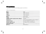
Page 38: ...cm 1 95 in Thickness 1 34 cm 0 53 in Weight 52 0 g 1 8 oz Volume 32 0 cm3 2 0 in3 Estimated battery longevity nominal settings 6 5 years Power source Carbon monofluoride silver vanadium oxide cell Connector strength Exceeds EN 45502 1 requirements Program storage capacity 15 programs with 1 stim set per lead Upgradeable features Yes MRI status MR Conditional ...

Page 39: ...ance For information on how additional settings may impact the longevity of the device please contact Technical Support The IPG has the following operating parameters Table 4 Operating parameters for the IPG Parameter Range Steps Pulse width 40 1000 µs 10 µs 40 500 µs range 50 µs 500 1000 µs range Frequency 4 80 Hz 2 Hz Amplitude 0 6 000 mA 0 025 0 400 mA NOTE The maximum current depends on the im...

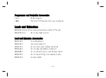
Page 40: ...ponents NOTE Not all models are available in all countries Contact your local representative for more information IPGs 3664 Proclaim DRG implantable pulse generator IPG Accessories 7108 Port plug DRG Programmers and Controllers 3874 St Jude Medical Clinician Programmer App 3875 St Jude Medical Patient Controller App ...

Page 41: ... standard and SlimTip leads MN20550 50 50 cm lead extension kit Lead and Extension Accessories MN15000 Tunneling tool kit MN22050 Lead accessories kit MN22150 22 cm small curve delivery sheath kit MN23650 22 cm big curve delivery sheath kit MN23850 22 cm Axium small curve delivery sheath MN23950 22 cm Axium big curve delivery sheath MN24000 Curved needle ...

Page 42: ...s regulatory statements about your product Disposal Guidelines for Battery Powered Devices This device contains a battery and a label is affixed to the device in accordance with European Council directives 2002 96 EC and 2006 66 EC These directives call for separate collection and disposal of electrical and electronic equipment and batteries Sorting such waste and removing it from other forms of w...

Page 43: ...erence to radio communications However there is no guarantee that interference will not occur in a particular installation If this equipment does cause harmful interference to radio or television reception which can be determined by turning the equipment off and on the user is encouraged to try to correct the interference by one or more of the following measures Reorient or relocate the receiving ...

Page 44: ...SS standard s Operation is subject to the following two conditions 1 this device may not cause interference and 2 this device must accept any interference including interference that may cause undesired operation of the device Identification Information for Product Registration This device has a label that contains among other information a product identifier in the following format Table 5 Regist...

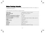
Page 45: ...na type Embedded patch antenna in header Antenna dimensions 8 1 mm x 5 1 mm x 4 9 mm Modulation GFSK Magnetic field strength at 2 m distance 16 3 µA m Electric field strength at 2 m distance 6 1 mV m Output power EIRP 1 mW 0 dBm typical 10 mW 10 dBm maximum Range 1 2 m typical Center frequency 2 44 GHz Channel 40 logical channels Bandwidth 2 MHz per channel Data flow Bi directional Protocol Blueto...

Page 46: ...ns a radio transmitter receiver with the following parameters Radio transmitter parameters Frequency range 2 4000 to 2 4835GHz Bandwidth 15dB 2 398to 2 4855GHz Channel 40 logical channels using AFH Modulation GFSK Radiated output power 10 mW 10 dBm maximum Magnetic field strength at 2 m distance 16 3 µA m Duty cycle Variable but low 5 Semi duplex capability ...

Page 47: ...ty of service QoS vary depending on the use environment operating room recovery room and home environment After the clinician programmer or patient controller is paired with a generator the Bluetooth wireless technology symbol is visible on the clinician programmer or patient controller in the upper right hand corner of the screen When the Bluetooth Smart wireless technology connection is not acti...

Page 48: ... at the same time A unique key for each unit that is checked during each transmission Built in pairing that specifies valid and legitimate pairing among units Proprietary authentication in addition to the pairing procedure specified in Bluetooth Smart wireless technology which includes an element of proximity A proprietary algorithm that detects and prevents an unauthorized user from attempting to...

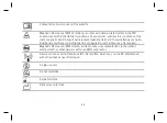
Page 49: ... phone or cordless phone at the same time NOTE Wireless communications equipment such as wireless home network devices mobile and cordless telephones and tablets can affect the device Appendix D Symbols and Definitions The following symbols may be used in this document and on some of the products and packaging Table 7 Symbols and definitions Symbol Definition Caution consult accompanying documents...

Page 50: ...nt magnetic field and the radiofrequency fields Additional conditions including specific configurations of the item may be required Magnetic Resonance MR Unsafe an item poses unacceptable risks to the patient medical staff or other persons within an MR environment Device contains a radio frequency RF transmitter which may cause RF interference with other devices near this device Single use only Do...

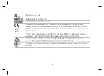
Page 51: ...ity Temperature limits for storage conditions Do not use if the product sterilization barrier or its packaging is compromised Catalog number Manufacturer Contents quantity Pulse generator Accessories Serial number Batch code ...

Page 52: ...lies with the essential requirements and other relevant provisions of these directives The full text of the European Union RE directive 2014 53 EU declaration of conformity is available at the following internet address www sjmglobal com euconformity Australian Communications and Media Authority ACMA and New Zealand Radio Spectrum Management RSM Regulatory Compliance Mark RCM This equipment is cer...

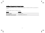
Page 53: ...duct Labels The following table shows additional symbols that may appear on the product labels for parts related to this kit Table 8 Additional symbols for product labels Symbol Definition Port plug DRG Implantable pulse generator ...

Page 54: ...E Mark Date The following table lists the year in which the CE mark was awarded from the applicable notified body by model number Table 9 Year in which CE mark was awarded Model Year Notified Body 3664 7108 2016 0086 ...

Page 55: ......
Page 56: ...gium 32 2 774 68 11 Australian Sponsor St Jude Medical Australia Pty Limited 17 Orion Road Lane Cove NSW 2066 Australia Manufacturing Site St Jude Medical Puerto Rico LLC Lot A Interior 2 Rd Km 67 5 Santana Industrial Park Arecibo PR 00612 USA Manufacturing Site St Jude Medical Operations M Sdn Bhd Plot 102 Lebuhraya Kampung Jawa Bayan Lepas Industrial Zone 11900 Penang Malaysia sjm com 600009573 ...

Reviews: