background image

26 

Protege IPG Clinician’s Manual

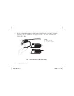
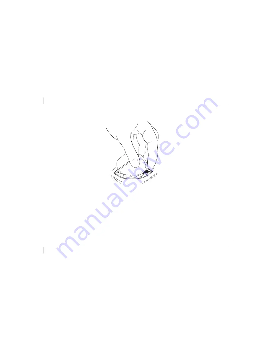
Figure 7: Place the IPG in the pocket

2.  Carefully coil any excess lead or extension behind the IPG in loops no 

smaller than 2.5 cm (1 in) in diameter to provide strain relief for the lead or 
extension and IPG connection.

37-4832-01A.indd   26

37-4832-01A.indd   26

1/30/2014   4:39:29 PM

1/30/2014   4:39:29 PM

Summary of Contents for Protege

Page 1: ...Clinician s Manual Protege Implantable Pulse Generator 37 4832 01A indd A 37 4832 01A indd A 1 30 2014 4 39 11 PM 1 30 2014 4 39 11 PM ...

Page 2: ...l or one of its subsidiaries ST JUDE MEDICAL and the nine squares symbol are trademarks and service marks of St Jude Medical Inc and its related companies 2013 St Jude Medical Inc All rights reserved For a listing of patents for St Jude Medical neuromodulation products visit http patent sjmneuro com 37 4832 01A indd B 37 4832 01A indd B 1 30 2014 4 39 15 PM 1 30 2014 4 39 15 PM ...

Page 3: ...nded Use 1 Indications for Use 1 Contraindications 2 Warnings 2 Precautions 5 Adverse Effects 10 Product Description 12 Contents of Package 13 Identifying the IPG 14 Directions for Use 15 Clinician s Manual 37 4832 01A indd i 37 4832 01A indd i 1 30 2014 4 39 16 PM 1 30 2014 4 39 16 PM ...

Page 4: ... Components 30 Maintaining the IPG Battery 31 Recharging the IPG Battery 33 Preserving the IPG When Not in Use 33 Customer Service Information 34 Appendix A Product Specifications 35 Protege IPG 35 Appendix B Regulatory Statements 37 Statement of FCC Compliance FCC ID PX 2001 37 Appendix C Symbols and Definitions 39 37 4832 01A indd ii 37 4832 01A indd ii 1 30 2014 4 39 16 PM 1 30 2014 4 39 16 PM ...

Page 5: ...ures The system is intended to be used with leads and associated extensions that are compatible with the system Indications for Use This neurostimulation system is indicated as an aid in the management of chronic intractable pain of the trunk and or limbs including unilateral or bilateral pain associated with the following failed back surgery syndrome and intractable low back and leg pain 37 4832 ...

Page 6: ...erapy Do not use short wave diathermy microwave diathermy or therapeutic ultrasound diathermy all now referred to as diathermy on patients implanted with a neurostimulation system Energy from diathermy can be transferred through the implanted system and cause tissue damage at the location of the implanted electrodes resulting in severe injury or death Diathermy is further prohibited because it may...

Page 7: ...he risk and possible interaction between a neurostimulation system and an implanted cardiac system such as a pacemaker or defibrillator Electrical pulses from a neurostimulation system may interact with the sensing operation of an implanted cardiac system causing the cardiac system to respond inappropriately To minimize or prevent the implanted cardiac system from sensing the output of the neurosti...

Page 8: ...the IPG if the case is pierced or ruptured because severe burns could result from exposure to battery chemicals IPG disposal Return all explanted IPGs to St Jude Medical for safe disposal see Disposing of Explanted Components IPGs contain lithium ion batteries as well as other potentially hazardous materials Do not crush puncture or burn the IPG because explosion or fire may result Product material...

Page 9: ... appropriately for neurostimulation Thorough psychiatric screening should be performed Patients should not be dependent on drugs and should be able to operate the neurostimulation system Infection Follow proper infection control procedures Infections related to system implantation might require that the device be explanted Implantation of two systems If two systems are implanted ensure that at lea...

Page 10: ...ted with nonadjacent multiple leads and patients who are sensitive to low stimulation thresholds may experience a momentary increase in their perceived stimulation which has been described by some patients as uncomfortable or jolting Patients should use caution when approaching such a device and should request assistance to bypass the device If they must proceed through the device patients should ...

Page 11: ...of infection and device malfunction Storage environment Store components and their packaging where they will not come in contact with liquids of any kind Handling and Implementation Expiration date An expiration date or use before date is printed on the packaging Do not use the system if the use before date has expired Care and handling of components Use extreme care when handling system component...

Page 12: ...e the patient leaves the surgery suite Device modification The equipment is not serviceable by the customer To prevent injury or damage to the system do not modify the equipment If needed return the equipment to St Jude Medical for service Hospital and Medical Environments High output ultrasonics and lithotripsy The use of high output devices such as an electrohydraulic lithotriptor may cause damag...

Page 13: ...ystem although no testing has been done and no definite information on radiation effects is available Sources of therapeutic radiation include therapeutic X rays cobalt machines and linear accelerators If radiation therapy is required the area over the implanted IPG should be shielded with lead Home and Occupational Environments Electromagnetic interference EMI Certain commercial electrical equipme...

Page 14: ...t sensations or motor disturbances including involuntary movement caused by stimulation at high outputs If either occurs turn off your IPG immediately Stimulation in unwanted places Paralysis weakness clumsiness numbness or pain below the level of the implant Persistent pain at the IPG site Seroma mass or swelling at the IPG site Allergic or rejection response to implant materials Implant migratio...

Page 15: ...Protege IPG Clinician s Manual 11 Battery failure 37 4832 01A indd 11 37 4832 01A indd 11 1 30 2014 4 39 17 PM 1 30 2014 4 39 17 PM ...

Page 16: ...ulation The IPG can deliver stimulation with a single program or with multiple programs called MultiStim programs New features can be introduced to the Protege system via software updates allowing for upgraded technology to be used A St Jude Medical external programmer may be needed for certain types of software updates to this product NOTE For more information about the neurostimulation system se...

Page 17: ...o the product documentation the Protege IPG kit Model 3789 contains the following items 1 IPG 1 pocket sizer 1 torque wrench Model 1101 2 port plugs Model 1111 1 tunneling tool Model 1112 37 4832 01A indd 13 37 4832 01A indd 13 1 30 2014 4 39 17 PM 1 30 2014 4 39 17 PM ...

Page 18: ...of the IPG in the header of the IPG For the Protege IPG the code is SJM ZNN where Z designates Model 3789 and NN designates the last two digits of the year of manufacture For example SJM Z14 designates a Protege IPG Model 3789 manufactured in 2014 Figure 1 Location of IPG code 37 4832 01A indd 14 37 4832 01A indd 14 1 30 2014 4 39 17 PM 1 30 2014 4 39 17 PM ...

Page 19: ...e to create an IPG pocket 1 Determine the site for the IPG ensuring that the lead is long enough to reach the pocket and provide a strain relief loop NOTE The IPG should be located in an area that the patient can easily reach with the programming wand Common sites for implantation are along the midaxillary line in the upper buttock along the posterior axillary line taking care to avoid the belt li...

Page 20: ...harge efficiently 2 Create the pocket so that the IPG is parallel to the skin surface and no deeper than 2 25 cm 0 9 in below the skin surface 3 Insert and remove the pocket sizer to ensure that the pocket is large enough to accommodate the IPG allowing enough extra room for a strain relief loop for each lead or extension 37 4832 01A indd 16 37 4832 01A indd 16 1 30 2014 4 39 19 PM 1 30 2014 4 39 ...

Page 21: ...continued to the IPG pocket site The following steps outline the suggested procedure to tunnel from the lead anchor site to the IPG pocket CAUTION Use extreme care so as not to damage a lead with the sharp point of the tunneling tool NOTE The tunneling tool is malleable and can be bent to conform to the contour of the patient s body 1 With the cannula sleeve in place on the tunneling tool create a...

Page 22: ... Figure 2 Suggested tunnel to the IPG pocket 2 Withdraw the tunneling tool from the cannula sleeve leaving the cannula sleeve in the subcutaneous tunnel 37 4832 01A indd 18 37 4832 01A indd 18 1 30 2014 4 39 19 PM 1 30 2014 4 39 19 PM ...

Page 23: ...Patients with nonadjacent leads may experience changes in perceived stimulation from theft detectors and metal screening devices The correct way to route multiple leads is as follows 1 2 Legend 1 Correct 2 Incorrect 37 4832 01A indd 19 37 4832 01A indd 19 1 30 2014 4 39 20 PM 1 30 2014 4 39 20 PM ...

Page 24: ...ite and then to the IPG pocket Multiple leads may be placed in the same tunnel 1 2 3 Legend 1 Leave cannula sleeve in place 2 Remove tunneling tool 3 Pull lead through cannula sleeve to IPG pocket Figure 3 Sequence of tunneling steps for SCS 4 Withdraw the cannula sleeve from the subcutaneous tunnel by passing it over the lead or leads taking care not to cause traction on them 37 4832 01A indd 20 ...

Page 25: ...e in contact with body fluid or saline thoroughly clean the contacts with sterile deionized water or sterile water for irrigation and dry them completely CAUTION Observe these cautions when performing the following step Do not bend the lead sharply or it may be damaged Do not loosen the setscrew in the connector more than a quarter turn at a time while trying to insert the lead Retracting the sets...

Page 26: ... into the IPG header until all of the contact bands are fully inside the connector assembly and hidden from view 1 2 Legend 1 Fully inserted 2 Not fully inserted Figure 4 Insert the lead fully into the IPG header 37 4832 01A indd 22 37 4832 01A indd 22 1 30 2014 4 39 24 PM 1 30 2014 4 39 24 PM ...

Page 27: ... the torque wrench through the septum and tighten the setscrew turning it clockwise until the wrench clicks Figure 5 Tighten the setscrew clockwise 4 Remove the torque wrench and check the septum to ensure that it closed If the septum did not close gently reseat the septum flaps 37 4832 01A indd 23 37 4832 01A indd 23 1 30 2014 4 39 26 PM 1 30 2014 4 39 26 PM ...

Page 28: ...revious steps If implanting a single lead only insert the header port plug into the unused port and use the torque wrench to tighten the setscrew until it clicks Figure 6 Insert the port plug 37 4832 01A indd 24 37 4832 01A indd 24 1 30 2014 4 39 28 PM 1 30 2014 4 39 28 PM ...

Page 29: ...l facing toward the skin or it may not communicate or recharge If using more than one IPG implant them at least 20 cm 8 in apart Putting them too close together may interfere with the patient programmer s ability to communicate with each IPG separately 1 Place the IPG into the IPG pocket at a depth not to exceed 2 25 cm 0 9 in with the label facing the skin surface 37 4832 01A indd 25 37 4832 01A ...

Page 30: ...ocket 2 Carefully coil any excess lead or extension behind the IPG in loops no smaller than 2 5 cm 1 in in diameter to provide strain relief for the lead or extension and IPG connection 37 4832 01A indd 26 37 4832 01A indd 26 1 30 2014 4 39 29 PM 1 30 2014 4 39 29 PM ...

Page 31: ... closing to ensure proper positioning of the lead or leads and that it is straight with no sharp bends or kinks 5 Connect the communication wand to the patient programmer place the wand in a sterile bag and position the wand over the IPG site 6 Ensure that the patient programmer achieves effective communication with the IPG and that the system is operational NOTE IPG output may not be identical to...

Page 32: ... lead or extension or the component may be damaged 7 Ensure that the IPG is away from the pocket incision suture line close the pocket incision and apply the appropriate dressings Figure 8 Close the pocket incision 37 4832 01A indd 28 37 4832 01A indd 28 1 30 2014 4 39 31 PM 1 30 2014 4 39 31 PM ...

Page 33: ...pen the IPG implant site per normal surgical procedure 3 Insert the torque wrench through the septum of the IPG header and loosen the setscrew by turning it counterclockwise CAUTION When performing the following step do not bend the lead or extension sharply or it may be damaged 4 Gently remove the lead or extension from the IPG header then clean and dry all connections ensuring they are free of f...

Page 34: ...sposing of Explanted Components Explanted components should be returned to St Jude Medical for proper disposal To return an explanted component place it in a container or bag marked with a biohazard label and coordinate the return with your St Jude Medical representative or Customer Service 37 4832 01A indd 30 37 4832 01A indd 30 1 30 2014 4 39 33 PM 1 30 2014 4 39 33 PM ...

Page 35: ...e stimulation settings and length of time since the last recharge The following graph shows how the rechargeable battery depletes over time 1 2 3 4 5 6 Legend 1 Battery capacity 2 Time 3 Battery fully charged 4 Recharge notice 5 Stimulation stops 6 Recharge within 30 to 90 days Figure 9 IPG battery depletion over time 37 4832 01A indd 31 37 4832 01A indd 31 1 30 2014 4 39 33 PM 1 30 2014 4 39 33 P...

Page 36: ...st ten years of practical recharging In other words a ten year old device will maintain at least 24 hours of continuous therapy between recharges Depending on the patient s stimulation parameters the device will continue to operate for months to years Patients may experience a significantly longer device life before recharging is determined to be impractical if they use lower stimulation parameters...

Page 37: ... to 90 days of its full discharge the charger may not be able to recharge it and it will have to be surgically replaced to resume therapy Preserving the IPG When Not in Use To preserve the IPG when discontinuing stimulation for an extended period of time follow these steps 1 Recharge the battery to its maximum capacity before turning off the IPG 2 Recharge the battery to its maximum capacity every...

Page 38: ...neuromodulation product including technical service or repairs contact Customer Service using the following information St Jude Medical 6901 Preston Road Plano TX 75024 USA 800 727 7846 972 309 8000 972 309 8150 Fax 37 4832 01A indd 34 37 4832 01A indd 34 1 30 2014 4 39 35 PM 1 30 2014 4 39 35 PM ...

Page 39: ...gth 5 3 cm 2 09 in Thickness 0 95 to 1 1 cm 0 37 to 0 43 in Weight 29 0 g 1 0 oz Volume 17 7 cm3 1 08 in3 Power source Rechargeable lithium ion cell Storage temperature 10 C 55 C 14 F 131 F Storage humidity 10 90 noncondensing Storage pressure 70 150 kPa 10 2 21 8 psi Connector strength Exceeds EN45502 1 requirements 37 4832 01A indd 35 37 4832 01A indd 35 1 30 2014 4 39 36 PM 1 30 2014 4 39 36 PM...

Page 40: ...2 and 13 μs starting with 12 μs Frequency 2 200 Hz 2 Hz 200 500 Hz 10 Hz 500 1200 Hz 20 Hz Amplitude 0 25 5 mA max 12 V 0 1 1 0 mA NOTE The number of stim sets in use governs the maximum frequency 1200 number of stim sets NOTE The maximum current depends on the impedance frequency and pulse width settings 37 4832 01A indd 36 37 4832 01A indd 36 1 30 2014 4 39 37 PM 1 30 2014 4 39 37 PM ...

Page 41: ...nstalled and used in accordance with the instructions may cause harmful interference to radio communications However there is no guarantee that interference will not occur in a particular installation If this equipment does cause harmful interference to radio or television reception which can be determined by turning the equipment off and on the user is encouraged to try to correct the interferenc...

Page 42: ...itions This device may not cause harmful interference This device must accept any interference received including interference that may cause undesired operation Modifications not expressly approved by the manufacturer could void the user s authority to operate the equipment under FCC rules 37 4832 01A indd 38 37 4832 01A indd 38 1 30 2014 4 39 38 PM 1 30 2014 4 39 38 PM ...

Page 43: ...ion of the seriousness of the situation A warning alerts the user to a situation which if not avoided could result in 1 death or serious injury 2 serious or adverse reactions or 3 safety hazards A caution alerts the user to a situation which if not avoided may result in 1 minor or moderate injury or 2 damage to the equipment or other property This symbol advises the reader to consult this document...

Page 44: ...Denotes temperature limits for storage conditions Denotes humidity limits Denotes pressure limits Denotes do not use if the product sterilization barrier or its packaging is compromised Denotes catalog number Denotes manufacturer 37 4832 01A indd 40 37 4832 01A indd 40 1 30 2014 4 39 38 PM 1 30 2014 4 39 38 PM ...

Page 45: ...entory item SN Denotes serial number Denotes batch code Rx only Denotes for prescription use only Denotes ethylene oxide gas sterilization EC REP Denotes authorized European representative Denotes European conformity Denotes the EU notified body number for AIMD 37 4832 01A indd 41 37 4832 01A indd 41 1 30 2014 4 39 47 PM 1 30 2014 4 39 47 PM ...

Page 46: ...42 Protege IPG Clinician s Manual 37 4832 01A indd 42 37 4832 01A indd 42 1 30 2014 4 39 56 PM 1 30 2014 4 39 56 PM ...

Page 47: ...Protege IPG Clinician s Manual 43 37 4832 01A indd 43 37 4832 01A indd 43 1 30 2014 4 39 56 PM 1 30 2014 4 39 56 PM ...

Page 48: ...8150 Fax St Jude Medical Australia Pty Limited 17 Orion Road Lane Cove NSW 2066 Australia 61 2 9936 1200 61 2 9936 1222 Fax St Jude Medical Coordination Center BVBA The Corporate Village Da VinciIaan 11 Box F1 1935 Zaventem Belgium 32 2 774 68 11 32 2 772 83 84 Fax ATRIAL FIBRILLATION CARDIAC RHYTHM MANAGEMENT CARDIOVASCULAR NEUROMODULATION FEB 14 37 4832 01A indd 44 37 4832 01A indd 44 1 30 2014 ...

Reviews: