STA309A
Registers
Doc ID 13855 Rev 4
27/67
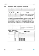
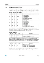
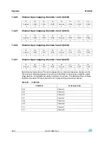
7.2.4 Configuration
register D (0x03)
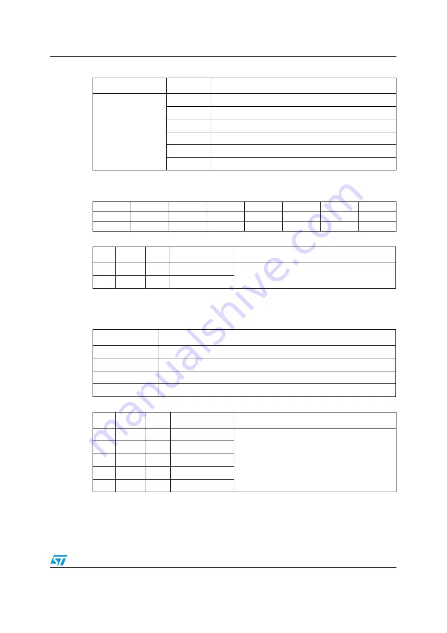
The DDX power output mode selects how the DDX output timing is configured. Different
power devices use different output modes. The STA50x recommended use is OM = 10.
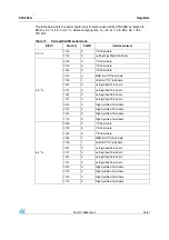
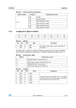
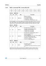
64 * fs
0000
I
2
S data
0001
Left-justified data
0010
Right-justified 24-bit data
0011
Right-justified 20-bit data
0100
Right-justified 18-bit data
0101
Right-justified 16-bit data
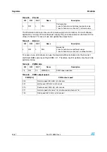
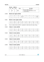
Table 20.
SAO serial clock (continued)
BICKI = BICKO
SAO[3:0]
Interface data format
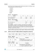
D7
D6
D5
D4
D3
D2
D1
D0
MPC
CSZ4
CSZ3
CSZ2
CSZ1
CSZ0
OM1
OM0
1
1
0
0
0
0
1
0
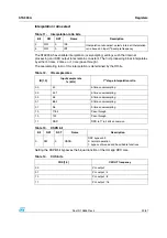
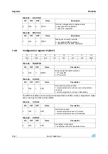
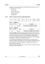
Table 21.
OM bits
Bit
RW
RST
Name
Description
0
RW
0
OM0
DDX power output mode: selects configuration of
DDX output.
1
RW
1
OM1
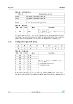
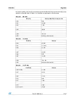
Table 22.
Output stage mode
OM[1:0]
Output stage - mode
00
STA50x/STA51xB - drop compensation
01
Discrete output stage - tapered compensation
10
STA50x/STA51xB - full power mode
11
Variable drop compensation (CSZn bits)
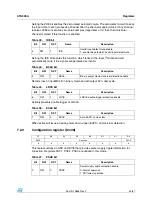
Table 23.
CSZ bits
Bit
RW
RST
Name
Description
2
RW
0
CSZ0
Contra size register: when OM[1,0] = 11, this register
determines the size of the DDX compensating pulse
from 0 clock ticks to 31 clock periods.
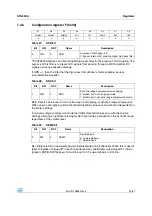
3
RW
0
CSZ1
4
RW
0
CSZ2
5
RW
0
CSZ3
6
RW
1
CSZ4

