
STA309A
Registers
Doc ID 13855 Rev 4
53/67
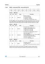
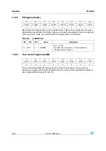
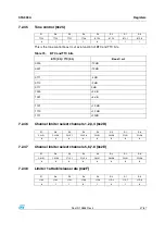
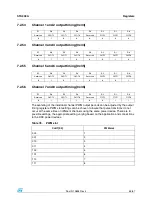
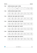
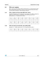
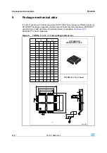
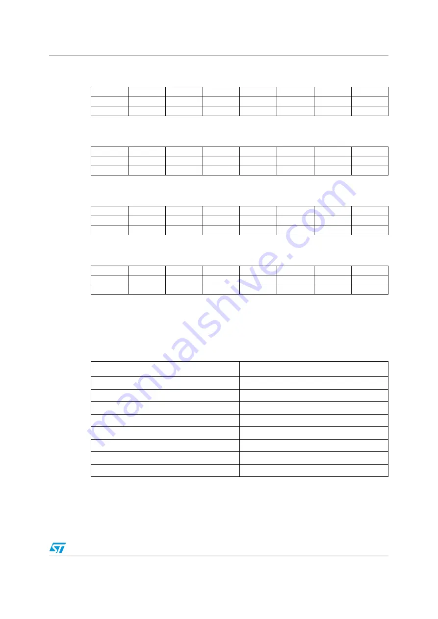
7.2.53
Channel 1 and 2 output timing (0x33)
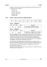
7.2.54
Channel 3 and 4 output timing (0x34)
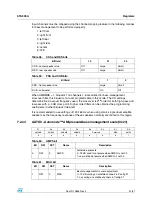
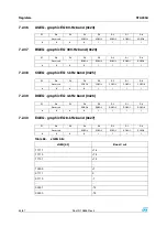
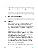
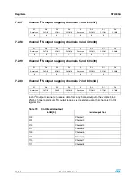
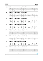
7.2.55
Channel 5 and 6 output timing (0x35)
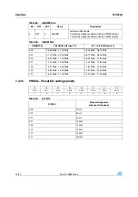
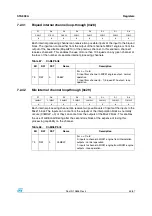
7.2.56
Channel 7 and 8 output timing (0x36)
The centering of the individual channel PWM output periods can be adjusted by the output
timing registers. PWM slot settings can be chosen to insure that pulse transitions do not
occur at the same time on different channels using the same power device. There are 8
possible settings, the appropriate setting varying based on the application and connections
to the DDX power devices.
D7
D6
D5
D4
D3
D2
D1
D0
Reserved
C2OT2
C2OT1
C2OT0
Reserved
C1OT2
C1OT1
C1OT0
0
1
0
0
0
0
0
0
D7
D6
D5
D4
D3
D2
D1
D0
Reserved
C4OT2
C4OT1
C4OT0
Reserved
C3OT2
C3OT1
C3OT0
0
1
1
0
0
0
1
0
D7
D6
D5
D4
D3
D2
D1
D0
Reserved
C6OT2
C6OT1
C6OT0
Reserved
C5OT2
C5OT1
C5OT0
0
1
0
1
0
0
0
1
D7
D6
D5
D4
D3
D2
D1
D0
Reserved
C8OT2
C8OT1
C8OT0
Reserved
C7OT2
C7OT1
C7OT0
0
1
1
1
0
0
1
1
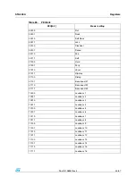
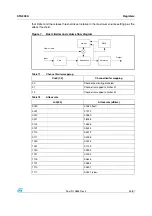
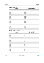
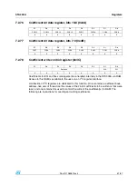
Table 78.
PWM slot
CnOT[2:0]
PWM slot
000
1
001
2
010
3
011
4
100
5
101
6
110
7
111
8


