Hardware layout and configuration
UM0686
12/58
Doc ID 15451 Rev 1
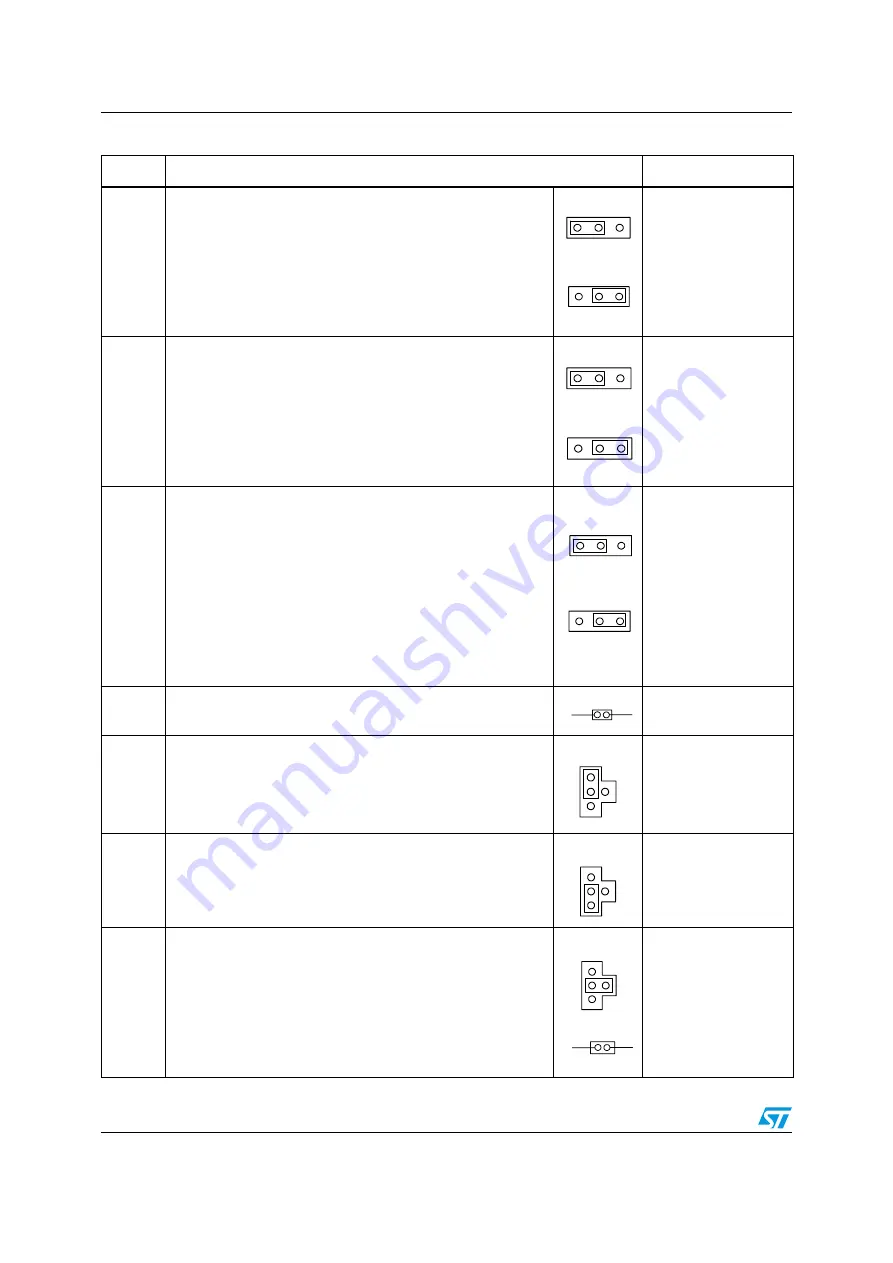
JMP8
MC sub2 PWM WL is enabled when JMP8 is configured as
shown:
MC sub1 EncIndex is enabled when JMP8 is configured as
shown:
JMP9
MC sub2 PWM VL is enabled when JMP9 is configured as
shown:
MC sub1 EncB is enabled when JMP9 is configured as shown:
JMP10
MC sub2 PWM UL is enabled when JMP10 is configured as
shown:
MC sub1 EncA is enabled when JMP10 is configured as shown:
JP13
MC main PFC Vac is enabled when JP13 is configured as
shown:
DAC
JP14
MC sub2 emergency stop is enabled when JP14 is configured
as shown:
JTAG, SPI1
JP15
MC sub2 PWM URef is enabled when JP15 is configured as
shown:
JTAG, SPI1
JP16,
JP5
MC main PFC Sync1 is enabled when JP16 is configured as
shown. JTAG debugging is disabled when JP16 is fitted
between the 2—4 pins.
JP5 fitted allows a PFC synchronization signal to be redirected
to the timer 3 input capture 1 pin, in addition to the timer 3
external trigger input.
Default setting: fitted
JTAG, SPI1
Table 6.
Motor control-related jumpers (continued)
Jumper
Description
Multiplexed peripheral
JMP8
1 2
3
JMP8
1 2
3
JMP9
1 2
3
JMP9
1 2
3
JMP10
1 2
3
JMP10
1 2
3
JP13
JP14
1
2
3
4
JP15
1
2
3
4
JP16
1
2
3
4
JP5
www.BDTIC.com/ST


