Hardware layout and configuration
UM0686
6/58
Doc ID 15451 Rev 1
1
Hardware layout and configuration
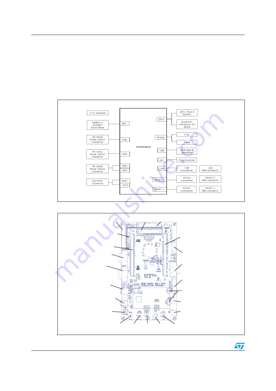
The STEVAL-IHM022V1 demonstration board is designed around the STM32F103ZE in
144-pin TQFP package. The hardware block diagram in
illustrates the connection
between the STM32F103ZE peripherals and connectors/devices on the board (LCD, SPI
Flash, USART, USB, CAN bus, I
2
C bus and motor control). The board layout diagram in
shows the location of the features on the demonstration board.
Figure 2.
Hardware block diagram
Figure 3.
STEVAL-IHM022V1 demonstration board layout
AM0
3
527v1
AM0
3
52
8
v1
CON8
Motor Control Main
CON10
Motor Control Sub2
CON14
Motor Control
Sub2 Aux
CON3
Extension Connector
P3
USART1
CON11
USB
CON12
+5V power
CON13
+5V power
S1
Reset
SW2
Wake-up
SW1
Tamper
U1
Joystick
SW3
Key
RV1
Potentiometer
CON5
Trace
CON6
JTAG
P1
CAN
CON2
I2C/IOS
CON1
Extension
Connector
CON4
Color LCD connector
P2
USART2
www.BDTIC.com/ST


