Hardware layout and configuration
UM2469
18/59
UM2469 Rev 1
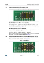
7.4.5
Supplying the board from an external power supply through USB FS
A 5 V DC external power supply is connected to USB OTG FS Micro-AB connector CN18
(5 V power source on silkscreen “USB_FS”, see
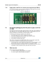
Figure 12. CN8 (USB_FS)
7.5 Programming/debugging
when
the power supply is not from
ST-LINK
It is mandatory to power the board first using CN3 (E5V) or CN12 (VIN) or CN18 (USB FS) or
CN19 (USB_HS), then connecting the USB cable to the PC. Proceeding this way ensures
that the enumeration succeeds thanks to the external power source.
The following power sequence procedure must be respected:
1.
Connect the jumper CN8 on (E5V) or (USB_HS) or (USB_FS)
2. Connect the external power source to CN3 or CN12 or CN18 or CN19
3. Check that the red LED LD2 is turned ON
4. Connect the PC to USB connector CN1
If this order is not respected, the STM32F7308-DK Discovery board may be powered by
V
BUS
first from ST-LINK and the following risks may be encountered:
1.
If more than 500 mA current is needed by the board, the PC may be damaged or current
can be limited by PC. As a consequence the board is not powered correctly.
2. 500 mA is requested at the enumeration: if the PC cannot provide such current, there is
a risk that the request is rejected and the enumeration does not succeed.
7.6 Clock
sources
Up to 2 clock sources as described below:
•
X2, 25 MHz oscillator for STM32F730I8K6 microcontroller.
•
X3, 32 KHz crystal for STM32F730I8K6 embedded RTC
06Y9
h^&
^


