Hardware layout and configuration
UM2469
16/59
UM2469 Rev 1
•
If the host is not able to provide the requested current, the enumeration fails. Therefore
the ST890 remains OFF and the STM32 part including the extension board is not
powered. As a consequence the red LED LD2 remains turned OFF. In this case it is
mandatory to use an external power supply.
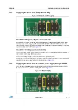
Figure 8. CN8 (ST-LINK)
Note:
In case the STM32F7308-DK board is powered by a USB charger, there is no USB
enumeration, so the led LD2 remains set to OFF permanently and the board is not powered.
Only in this specific case, the resistor R5 needs to be soldered, to allow the board to be
powered anyway.
The LED LD2 is lit when the STM32F7308-DK board is powered by the 5 V correctly.
Caution:
Do not connect a PC to ST-LINK (CN1) when R5 is soldered. The PC may be damaged or the
board not powered correctly.
7.4.2
Supplying the board through a charger connected to ST-LINK
The 5 V DC power charger is connected to USB STLINK (CN1). In this case if the
STM32F7308-DK board is powered by an external USB charger then the debug is not
available. If the PC is connected instead of the charger, then the limitation is no more
effective and the PC could be damaged (5 V power source on silkscreen “USB_STLINK”
see
).
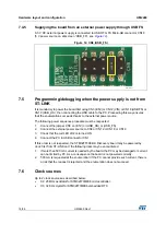
Figure 9. CN8 (USB_STLINK)
06Y9
^d>/E<
06Y9
h^^
d>/E<


