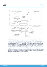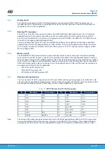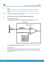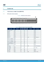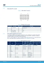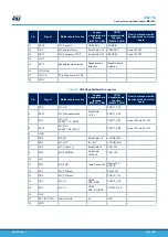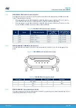
Moreover, the V
BUS
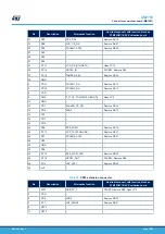
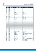
path on port 1 presents a discharge mechanism implemented by the T8 MOSFET and an RC
filter controlled by PB13 and the V
BUS
path on port 2 presents a discharge mechanism implemented by the T9
MOSFET and an RC filter controlled by PB14.
6.8.4
V
BUS
voltage-sensing and current-sensing stages
Each USB Type-C
®
port is equipped with a voltage-sensing and current-sensing stages which are matched with
the voltage sensing carried by the MCU ADC peripherals. Refer to
for details. They can monitor the right
power level applied to the V
BUS
port.
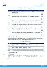
Table 19.
Voltage-sensing and current-sensing ADCs
Port
Vsense ADC
Isense ADC
Port 1
PB1
ADC_IN9
PB10
ADC_IN11
Port 2
PA3
ADC_IN3
PB12
ADC_IN16
6.8.5
CC management
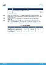
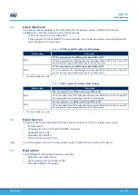
Dead battery, VCONN output, and fast role swap functions are supported on the CC signal of USB Type-C
®
port
1.
1. Dead battery enable
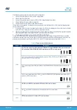
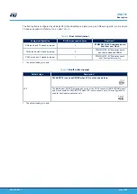
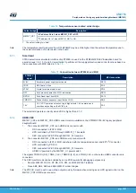
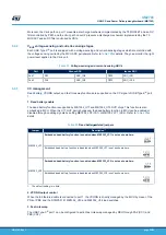
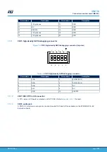
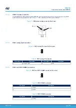
The dead battery function is supported by MB1352_U17 and MB1352_U16 OVP chips. This function is also
embedded in MCU. When the U17 OVP part is bypassed, the dead battery function in MCU can be enabled or
disabled through enabling signals by setting MB1352_JP2 (CC1) or MB1352_JP1 (CC2). Refer to
detail.
Table 20.
Dead battery
‑
related jumpers
Jumper
MB1352_JP1
Embedded dead battery function is enabled when MB1352_JP1 is set as shown here:
Embedded dead battery function is disabled when MB1352_JP1 is set as shown here:
MB1352_JP2
Embedded dead battery function is enabled when MB1352_JP2 is set as shown here:
Embedded dead battery function is disabled when MB1352_JP2 is set as shown here:
1. The default setting is in bold.
2. VCONN output control
When the full-featured cable is connected to port 1, the VCONN is directly managed by the MCU by mean of the
PD4 or PB9, and the STMPS2161 MB1352_U10 and MB1352_U14 load switches.
3. Fast role swap
The USB Type-C
®
port 1 can be configured to action fast role swap managed by MCU through PA2 (CC1) and
PB0 (CC2).
UM2783
USB-C® and Power Delivery daughterboard (MB1352)
UM2783
-
Rev 1
page 25/59

