6.3
Clock references
Two clock sources are available on the STM32G0C1E-EV Evaluation board for STM32G0C1VE and its
embedded RTC, and other clock sources for their peripherals.
•
32.768 kHz crystal X2 for embedded RTC
•
8 MHz crystal X3 for the STM32G0C1VE microcontroller. It can be disconnected by removing R46 and R47
when the internal RC clock is used.
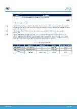
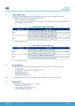
Table 6.
32 KHz crystal X2 related solder bridges
Solder bridge
Description
SB53
PC14 is connected to the 32KHz crystal when SB53 is OFF.
PC14 is connected to the CN9 extension connector when SB53 is ON. In such a case, R39
must be removed to avoid disturbance due to the 32 Khz quartz.
SB52
PC15 is connected to the 32KHz crystal when SB52 is OFF.
PC15 is connected to the CN9 extension connector when SB52 is ON. In such a case, R40
must be removed to avoid disturbance due to the 32Khz quartz.
1. The default setting is in bold.
Table 7.
8 MHz crystal X3 related solder bridges
Solder bridge
Description
SB55
PF0 is connected to an 8 MHz crystal when SB55 is OFF.
PF0 is connected to the CN10 extension connector when SB55 is ON. In such a case, R46
must be removed to avoid disturbance due to the 8 Mhz quartz.
SB54
PF1 is connected to an 8 MHz crystal when SB54 is OFF.
PF1 is connected to the CN10 extension connector when SB54 is ON. In such a case, R47
must be removed to avoid disturbance due to the 8 Mhz quartz.
1. The default setting is in bold.
6.4
Reset sources
The general reset of the STM32G0C1E-EV Evaluation board is active LOW. The reset sources include:
•
B1 Reset button
•
Debugging tools from CN14 and CN15 SWD connectors
•
Daughterboard on CN2
•
Embedded ST-LINK/V2-1
•
CN16 RS-232 connector for ISP
Note:
The JP20 jumper must be ON for reset handled by pin8 of CN16 RS-232 connector (CTS signal).
6.5
Boot option
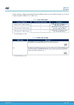
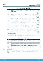
The STM32G0C1E-EV Evaluation board can boot from:
•
Embedded user Flash memory
•
System memory with boot loader for ISP
•
Embedded SRAM for debugging
UM2783
Clock references
UM2783
-
Rev 1
page 16/59


