6.6
Peripherals on mother board (MB1581)
6.6.1
Audio
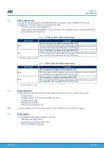
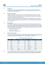
The STM32G0C1E-EV mother board (MB1581) supports stereo audio playback and microphone recording by an
external headset connected to the CN18 audio jack. The audio play is connected to the DAC output of the MCU
through an audio amplifier, and the microphone on the headset is connected to the ADC input of the MCU through
a microphone amplifier. The audio amplifier can be enabled or disabled by the JP25 setting and mono/stereo
playback can be chosen by the JP19 setting. Refer to
Table 10.
Audio related jumpers
Jumper
Description
JP25
Speaker amplifier U17 is enabled when JP25 is ON.
Speaker amplifier U17 is disabled when JP25 is OFF.
JP23
PA4 is connected to VIN1 of the audio amplifier when JP23 is ON.
PA4 is disconnected to VIN1 of the audio amplifier when JP23 is OFF.
JP19
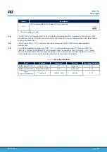
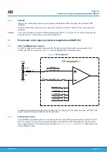
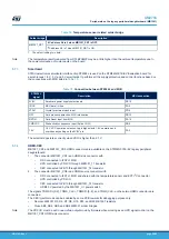
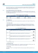
Mono playback is enabled when JP19 is set as shown here:
Stereo playback is enabled when JP19 is set as shown here:
1. The default setting is in bold.
The audio amplifier operates correctly when VDD is superior to 2.2 V and the microphone amplifier operates
correctly when VDD is superior to 2.7 V
6.6.2
RS-232 and RS-485
Communication through RS-232 (With Hardware flow control CTS and RTS) and RS-485 are supported by the
CN16 D-type 9-pins RS-232/RS-485 connector, which is connected to USART1 of MCU on the STM32G0C1E-EV
Evaluation board. The Bootloader_RESET (shared with CTS signal) and Bootloader_BOOT0 (shared with DSR
signal) signals are added to the CN16 RS-232 connector for ISP support.
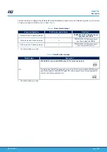
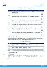
By default, PC4 and PC5 are connected as TX and RX signals. PA9 and PA10 can also be connected as these
two signals for bootloader which is NOT supported on PC4 and PC5 by the setting of jumpers in
.
UM2783
Peripherals on mother board (MB1581)
UM2783
-
Rev 1
page 18/59

