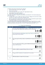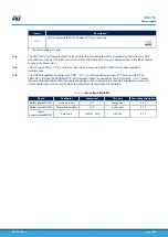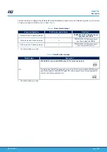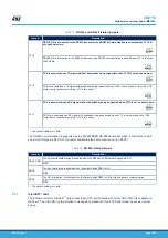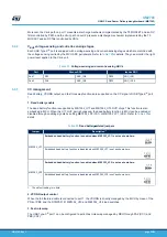
Table 14.
Temperature-sensor related solder bridge
Solder bridge
MB1351_SB7
I
2
C address A0 is 0 when MB1351_SB7 is OFF.
I
2
C address A0 is 1 when MB1351_SB7 is ON.
1. The default setting is in bold.
Note:
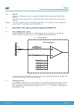
The temperature result measured from STLM75M2F may be a little higher than the ambient temperature due to
the power dissipation of components on the board.
6.7.3
Smartcard
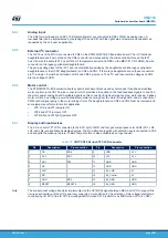
STMicroelectronics smartcard interface chip ST8024L is used on the STM32G0C1E-EV Evaluation board for
asynchronous 1.8 V, 3 V, and 5 V smartcards. It performs all the supply protection and control functions based on
the connections with MCU listed in
Table 15.
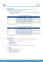
Connection between ST8024L and MCU
ST8024L
signal
Description
MCU connection
5V/3V
Smartcard power supply selection pin
PB15
I/OUC
MCU data I/O line
PA2
XTAL1
Crystal or external clock input
PD4
OFF
Card presence detection, MCU interruption
PB12
RSTIN
Card Reset Input from MCU
PA15
CMDVCC
Start activation sequence input (Active LOW)
PB0
1.8V
1.8 V VCC operation selection. Logic high selects 1.8 V operation and
overrides any setting on the 5V/3V pin.
PA3
The smartcard operates correctly when VDD is higher than 2.7 V.
6.7.4
HDMI-CEC
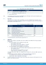
MB1351_CN1 and MB1351_CN3 HDMI connectors are available on the STM32G0C1E-EV legacy peripheral
daughterboard.
1.
The connector MB1351_CN1 is an HDMI sink connector with:
–
DDC connected to I2C2 of MCU
–
HPD controlled by PD2 I/O through MB1351_T1 transistor
–
CEC connected to PB10 through MB1351_T4 transistor
2.
The connector MB1351_CN3 is an HDMI source connector with:
–
DDC connected to I2C1 of MCU and shared with the temperature sensor and EXT I
2
C connector
–
HPD controlled by PD3 I/O
–
CEC connected to PB10 through MB1351_T4 transistor
–
HDMI 5 V powered by the MB1351_U1 power switch
The signals TDMS D+[0..2], T, TDMS D-[0..2], and TDMS_CLK- on these two HDMI connectors are
connected.
The CEC injector mode can be enabled by some PCB reworks for debugging purpose only:
•
Remove MB1351 R3, R4, R7, R9, R10, R15, and R22 MB1351 resistors.
•
Close SB3, SB4, SB5, and SB6 MB1351 solder bridges.
Note:
The PD2 I/O must be set in open-drain output mode by firmware when working as an HPD signal control on the
MB1351_CN1 HDMI sink connector.
UM2783
Peripherals on the legacy peripheral daughterboard (MB1351)
UM2783
-
Rev 1
page 22/59


