Hardware description
and configuration
UM1910
6/12
DocID027979 Rev 1
2.1
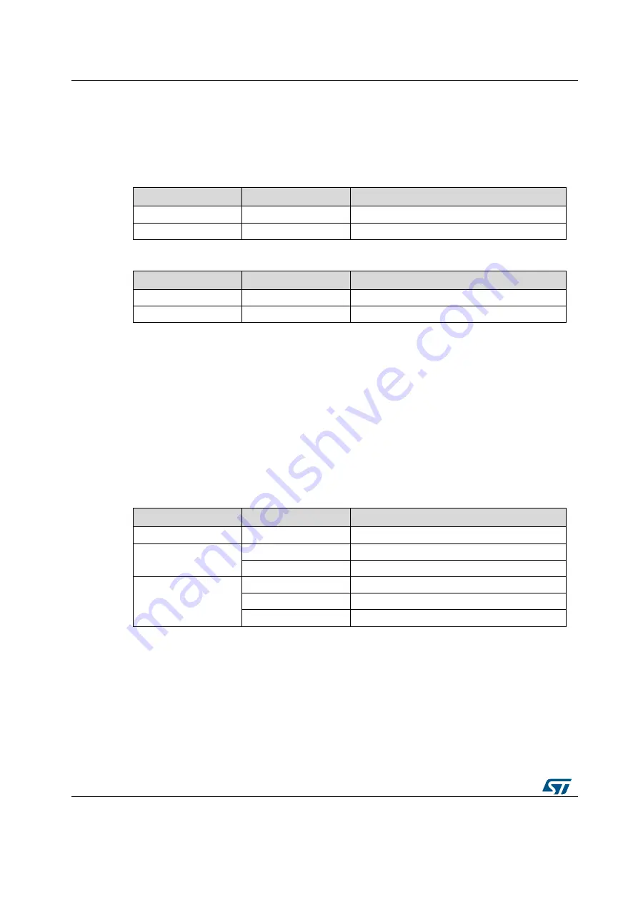
Selecting the chip select and clock lines of the SPI
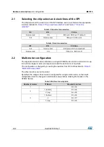
The chip select and the clock lines of the SPI interface can be selected via the appropriate
resistors indicated in
Table 3: "Chip select line selection"
Table 3: Chip select line selection
R9
R10
CS line
Not mounted
0 Ω
CN5 pin3, CN10 pin 17 (default)
0 Ω
Not mounted
CN8 pin 3, CN7 pin 32
Table 4: Clock line selection
R11
R12
SCK line
0 Ω
Not mounted
CN5 pin6, CN10 pin 9 (default)
Not mounted
0 Ω
CN9 pin 4, CN10 pin 31
2.2
Multi-motor configuration
The expansion boards can be stacked on a single STM32 Nucleo board in order to drive up
to the three stepper motors (one expansion board for each motor is required).
The configuration is changed by mounting the resistors from R3 to R8 as listed in
The other resistors are not mounted.
By default, the stepper driver board is configured for a single-motor setup, so the board
configuration must be changed in multi-motor setups before stacking the boards on the
STM32 Nucleo.
Table 5: Multi-motor setup table
Number of motors
Of Board
Mounted resistors
1
-
R3
– R8
2
1 (bottom)
R3
– R6
2 (top)
R4
– R8
3
1 (bottom)
R3
– R6
2
R4
– R7
3 (top)
R5
– R8


