UM1925
Hardware description
and configuration
DocID028121 Rev 1
9/17
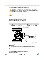
Both A+ (CN1 pin1) B+ (CN1 pin4)
Both A- (CN1 pin2) B- (CN1 pin3)
Table 6: Jumper selection
J1
J2
J3
J4
Disconnected
Disconnected
Connected
Connected
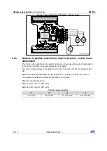
Figure 6: One DC motor bidirectional - higher current
2.2.4
Mode n °4: parallel connection for higher current - two unidirectional
DC motors
This mode is similar to mode 3 - the bidirectional DC motor is replaced by two
unidirectional DC motors
Motor A connected between
Both A+ (CN1 pin1) B+ (CN1 pin4)
GND
Motor B connected between
Both A- (CN1 pin2) B- (CN1 pin3)
GND
Table 7: Jumper selection
J1
J2
J3
J4
Disconnected
Disconnected
Connected
Connected


