Hardware description
and configuration
UM1925
6/17
DocID028121 Rev 1
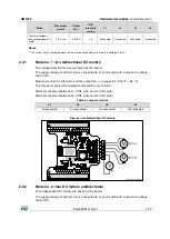
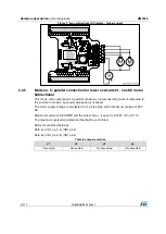
Figure 3: Overcurrent threshold versus resistor value (no paralleling)
When one of the paralleling modes is used (see
Section 2.2: "Selecting the mode"
), the
actual OCD threshold value may be scaled as indicated in
2.2
Selecting the mode
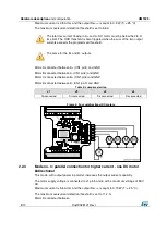
This board can drive 1 to 4 DC motors with several configurations.
The selection is done by Jumper J1 - J2 - J3 and J4, by default: all jumpers are not
populated.
The table below briefly summarizes the possible configurations:
Table 3: Board configuration summary
Mode
Max output
current
Output
R
DS(on)
OCD
threshold
scaling
J1
J2
J3
J4
Two bidirectional DC
motors
2.8 A rms
0.3 Ω
× 1
Disconnect
ed
Disconnect
ed
Disconnect
ed
Disconnect
ed
Four unidirectional
DC motors
2.8 A rms
0.3 Ω
× 1
(1)
Disconnect
ed
Disconnect
ed
Disconnect
ed
Disconnect
ed
High current parallel
one bidirectional DC
motor
5.6 A rms
0.15 Ω
× 2
Disconnect
ed
Disconnect
ed
Connected
Connected
High current parallel
two unidirectional DC
motors
5.6 A rms
0.15 Ω
× 2
Disconnect
ed
Disconnect
ed
Connected
Connected
Low current parallel
one DC motors
bidirectional
2.8 A rms
0.15 Ω
× 1
Connected
Connected
Disconnect
ed
Disconnect
ed
Low current parallel
two unidirectional DC
motors
2.8 A rms
0.15 Ω
× 1
Connected
Connected
Disconnect
ed
Disconnect
ed


