background image

UM1996 

Board

 schematics 


DocID028716 Rev 2 

13/29 


Figure 7: Auxiliary power supply circuit 


Figure 8: Sensing and Hall/Encoder circuit 


Figure 9: Analog conditioning and current protection circuit 


Summary of Contents for X-NUCLEO-IHM08M1

Page 1: ...ess mainly focus on the distribution of electronic components Line cards we deal with include Microchip ALPS ROHM Xilinx Pulse ON Everlight and Freescale Main products comprise IC Modules Potentiometer IC Socket Relay Connector Our parts cover such applications as commercial industrial and automotives areas We are looking forward to setting up business relationship with you and hope to provide you...

Page 2: ...he X NUCLEO IHM08M1 is fully configurable and ready to support different closed loop control scenarios based on sensorless or sensor mode control and it is compatible with three shunt or single shunt current sense measuring The L6398 IC driver used on this STM32 Nucleo expansion board is a single chip half bridge gate driver for the N channel power MOSFET This combination of the L6398 gate driver ...

Page 3: ...are settings 8 3 Board schematics 12 4 Circuit description 15 4 1 Power section 15 4 1 1 L6398 gate driver and STL220N6F7 STripFET F7 Power MOSFET 15 4 1 2 Overcurrent detection OCP and current sensing measurement 16 4 2 Analog section 17 4 2 1 Hall Encoder motor speed sensor 17 4 3 BEMF detection circuit 18 5 Bill of materials 19 6 X NUCLEO IHM08M1 STM32 PMSM FOC SDK parameters 27 7 Revision hist...

Page 4: ...716 Rev 2 3 29 List of tables Table 1 Jumper settings 8 Table 2 Screw terminals 8 Table 3 ST morpho connector CN7 9 Table 4 ST morpho connector CN10 10 Table 5 BoM 1 of 2 19 Table 6 BoM 2 of 2 23 Table 7 Document revision history 28 ...

Page 5: ...iary power supply circuit 13 Figure 8 Sensing and Hall Encoder circuit 13 Figure 9 Analog conditioning and current protection circuit 13 Figure 10 MCU pin out assignment 14 Figure 11 X NUCLEO IHM08M1 power section 16 Figure 12 X NUCLEO IHM08M1 OCP circuit 16 Figure 13 X NUCLEO IHM08M1 Current sensing circuit 1 of 3 17 Figure 14 X NUCLEO IHM08M1 Current sensing circuit 2 of 3 17 Figure 15 X NUCLEO ...

Page 6: ...ll compatible with ST Six Step or ST FOC control algorithm Full support for sensorless and sensor mode 3 shunt and 1 shunt configurable jumpers for motor current sensing Hall Encoder motor sensor connector and circuit Debug connector for DAC GPIOs etc Potentiometer available for speed regulation User LED Compatible with STM32 Nucleo boards Equipped with ST morpho connectors RoHS compliant 1 2 Targ...

Page 7: ...O IHM08M1 is able to proper drive a low voltage BLDC PMSM motor This section describes how to set up different hardware parts before writing and executing an application on the STM32 Nucleo board with the low voltage BLDC motor driver expansion board Figure 2 System functional hardware blocks 2 2 Building the system The X NUCLEO IHM08M1 expansion board Power block in the figure above is a complete...

Page 8: ... st com 1 Connect the three motor wires U V W to the J16 connector 2 To select the control algorithm 6 step or FOC ensure no voltage supply is connected On the STM32 NUCLEO board set jumpers JP1 open JP5 PWR on E5V side JP6 IDD closed On the X NUCLEO IHM08M1 expansion board set jumpers J9 open JP3 closed For 6 step control X CUBE SPN8 FW set jumpers JP1 and JP2 open J5 J6 on the 1 Sh side Keep cap...

Page 9: ...ommendation below Table 1 Jumper settings Jumper Permitted Configurations Default Condition JP1 Selection for pull up insertion BIAS in current sensing circuit OPEN JP2 Selection for operational amplifier gain modification in current sensing circuit OPEN JP3 Selection for enabling pull up in Hall Encoder detection circuit CLOSED J9 Selection to supply the STM32 Nucleo board through the X NUCLEO IH...

Page 10: ...nnect this power board to the STM32 Nucleo board All the MCU signal and power pins are available on the ST morpho connector For further details please refer to UM1724 document 5 12 STMicroelectronics morpho connector available on website www st com Table 3 ST morpho connector CN7 Pin Default Signal Solder Bridge 1 PC10 2 PC11 3 PC12 4 PD2 5 VDD 6 E5V 5 V for STM32 Nucleo supply R170 7 BOOT0 8 GND ...

Page 11: ...F1 PD1 32 PA4 DAC_Ch Potentiometer 1 R76 N M R181 33 VLCD VBAT 34 PB0 VL TIM1_CH2N R67 35 PC2 Temperature feedback R54 36 PC1 or PB9 2 Curr_fdbk_PhB R48 37 PC3 BEMF1 R59 38 PC0 or PB8 2 Curr_fdbk_PhC R50 Notes 1 By default the potentiometer is connected on PA4 For DAC usage remove resistor R181 2 Refer to user manual UM1724 Table 9 Solder bridges for further details Table 4 ST morpho connector CN1...

Page 12: ...CH1 R56 24 PB1 WL TIM1_CH3N R72 25 PB10 Encoder Z Hall H3 R84 26 PB15 4 UL TIM1_CH1N R86 27 PB4 CURRENT REF R77 28 PB14 3 BKIN R74 29 PB5 GPIO DAC PWM R85 30 PB13 2 GPIO DAC PWM R82 N M 31 PB3 Encoder B Hall H2 R81 32 AGND 33 PA10 WH TIM1_CH3 R70 34 PC4 BEMF2 R61 35 PA2 36 NC PF5 37 PA3 38 NC PF4 Notes 1 U5V is 5 V power from ST LINK V2 1 USB connector and it rises before 5 V 2 For NUCLEO F302R8 p...

Page 13: ...Board schematics UM1996 12 29 DocID028716 Rev 2 3 Board schematics Figure 5 Power section Figure 6 Current sensing and B emf circuit ...

Page 14: ...UM1996 Board schematics DocID028716 Rev 2 13 29 Figure 7 Auxiliary power supply circuit Figure 8 Sensing and Hall Encoder circuit Figure 9 Analog conditioning and current protection circuit ...

Page 15: ...Board schematics UM1996 14 29 DocID028716 Rev 2 Figure 10 MCU pin out assignment ...

Page 16: ...e also reducing internal capacitance and gate charge for faster and more efficient switching It features Among the lowest RDS on on the market 0 0014 Ω Excellent figure of merit FoM Low Crss Ciss ratio for EMI immunity High avalanche ruggedness Together these devices form the high current power platform for the BLDC motor The main supply voltage is provided through an external connector J1 and you...

Page 17: ...the MCU and the output generates a fault condition at the BKIN pin that goes to ground This pin connected to STM32 Nucleo board BKIN Timer function detects this condition and immediately disables the driving signals see the schematic below Figure 12 X NUCLEO IHM08M1 OCP circuit The current sensing inputs refer to the following three schematics are connected to the sensing resistors and you can cho...

Page 18: ...UCLEO IHM08M1 expansion board implements the Hall Encoder sensor detecting circuit for speed measurement the schematic for which is given in the figure below The motor sensor pin through the J3 connector and an analog circuit are connected to the STM32 Nucleo board in order to determine motor spin a 5 V and GND are also provided to power the sensors Jumper JP3 is available for sensors that require...

Page 19: ... state and we can detect BEMF zero crossing events by comparing the voltage of this phase with the center tap voltage This signal is acquired through an analog circuit embedded on the board as shown below Figure 17 X NUCLEO IHM08M1 BEMF detection circuit The X NUCLEO IHM08M1 expansion board provides the hardware for bus voltage sensing and temperature measurement This signal is acquired with a res...

Page 20: ...C7 15nF 10V 10V Ceramic Multilayer Capacitors X7R 10 4 3 C4 C6 C8 100pF 6 3V 6 3V Ceramic Multilayer Capacitors X7R 10 5 4 C10 C125 C 127 C129 10nF 10V 10V Ceramic Multilayer Capacitors X7R 10 6 2 C11 C13 100nF 100V Ceramic Multilayer Capacitors X7R 10 7 1 C14 4 7nF 10V Ceramic Multilayer Capacitors X7R 10 8 1 C18 10nF NM 10V Ceramic Multilayer Capacitors X7R 10 9 3 C20 C21 C2 2 10pF 10V Ceramic M...

Page 21: ...ramic Multilayer Capacitors X7R 10 16 3 C102 C108 C118 470nF 25V Ceramic Multilayer Capacitors X7R 10 17 3 C103 C109 C119 1uF 50V Ceramic Multilayer Capacitors X7R 10 18 6 C104 C105 C110 C111 C120 C121 NM 25V Ceramic Multilayer Capacitors X7R 10 19 2 C114 C123 330uF 63V Electrolytic Capacitor 0 2 20 1 D1 SMBJ48A TR Transil 21 16 D2 D3 D4 D 5 D6 D7 D8 D9 D10 D12 D21 D22 D2 3 D24 D25 D 26 BAT30KFILM...

Page 22: ...E MALE 2 54mm 30 1 J16 Motor Connector 3 way 6 35mm PCB terminal block 31 2 CN7 CN10 CN7 CN10 ST_MORPHO_1 9x2 ELEVATED SOCKET ST MORPHO CONNECTOR 38 PIN 19x2 32 2 CN6 CN9 CN6 CN9 8 PIN ELEVATED SOCKET 33 1 CN5 CN5 10 PIN ELEVATED SOCKET 34 1 CN8 CN8 6 PIN ELEVATED SOCKET 35 1 L3 8 2uH 520mA SMT power inductor 36 6 Q7 Q8 Q9 Q 10 Q11 Q12 STL220N6F7 60V 220A Power MOSFETS 37 3 R1 R6 R12 6 8 kΩ 0 1W S...

Page 23: ...1 44 1 R19 NTC 10kΩ NTC Thermistor 1 45 1 R20 4 7 kΩ 0 1W SMD RESISTOR 46 2 R21 R179 33 kΩ 0 1W SMD RESISTOR 47 13 R23 R27 R2 8 R29 R148 R151 R154 R157 R163 R166 R172 R175 R177 10 kΩ 0 1W SMD RESISTOR 48 3 R30 R31 R3 2 1 8 kΩ 0 1W SMD RESISTOR 49 3 R33 R34 R3 5 4 7 kΩ 0 1W SMD RESISTOR 50 3 R36 R37 R3 8 2 2 kΩ 0 1W SMD RESISTOR 1 51 3 R39 R40 R4 1 10 kΩ 0 125W SMD RESISTOR 52 1 R42 100 kΩ 1 2W TRI...

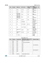
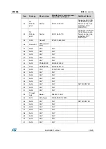
Page 24: ...er 63 1 U4 ST1S14PHR 50V 3A 3A Step down switching regulator 64 1 U19 LD1117S50TR Low Drop Voltage Regulator 65 3 U20 U21 U2 2 L6398 600V High voltage high and low side driver 66 4 U23 U24 U2 5 U26 LMV331 3 3V Low voltage comparators 67 4 Jumper Female 2 54mm jumper Table 6 BoM 2 of 2 Item Package Manufacturer Manufacturer s ordering code Orderable Part Number Additional Notes 1 0603 ANY ANY 2 080...

Page 25: ...3 STMicroelectr onics BAT30KFILM 22 SMD 0603 Lite on LTST C193KRKT 5A 23 SOD 123 STMicroelectr onics STPS0560Z 24 TH 2 54mm pitch any Mount with female jumper 25 TH 6 35 mm pitch Phoenix Contact 1714955 26 TH 2 54mm pitch any 27 TH Vero Technologies 20 2137 28 Tin drop JUMPER in 1sh direction See assembly drawing 29 TH 2 54mm pitch any 30 TH 6 35 mm pitch Phoenix Contact 1714968 31 TH 2 54mm pitch...

Page 26: ... MOUNTED 35 SMD Coilcraft EPL2010 822MLB 36 PowerFlat STMicroelectr onics 37 0603 ANY ANY 38 0603 ANY ANY 39 0603 ANY ANY 40 0603 ANY ANY 41 0603 ANY ANY 42 0603 PANASONIC ERJ3EKF1693V 43 0603 PANASONIC ERJ3EKF9311V 44 0402 TDK NTCG103JF103F 45 0603 ANY ANY 46 0603 ANY ANY 47 0603 ANY ANY 48 0603 ANY ANY 49 0603 ANY ANY NOT MOUNTED 50 0603 ANY ANY 51 0805 ANY ANY 52 Through hole Bourns 3386G 1 104...

Reviews: