DocID028405 Rev 1
15/28
UM1955
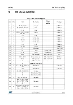
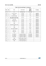
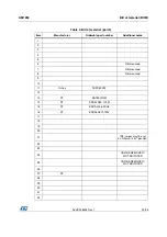
Window comparator configuration
28
7
Window comparator configuration
The window comparator configuration allows the user to compare a signal to two threshold
voltages. When the signal is out of the required voltage range, the output of the operational
amplifier toggles.
7.1 Schematic
diagram
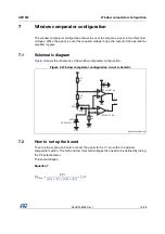
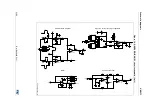
Figure 9
shows the schematic of the window comparator configuration.
Figure 9. Window comparator configuration circuit schematic
7.2
How to set up the board
To set up the expansion board, connect the signal to the “in” pin within the window
comparator section. The high and low threshold voltages then need to be defined by tuning
the P2 potentiometer.
Threshold voltages:
Equation 7
9FF
Q)
&
*1'
*1'
9FF
:LQBLQ
N
3
'
'
N
5
N
5
N
5
9
9
768,37 $
768,37 %
(6'
(6'$/&90
*1'
*63*',


