DocID028405 Rev 1
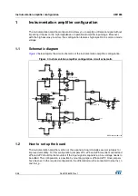
17/28
UM1955
Prototyping area
28
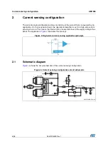
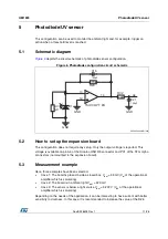
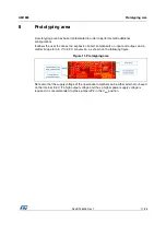
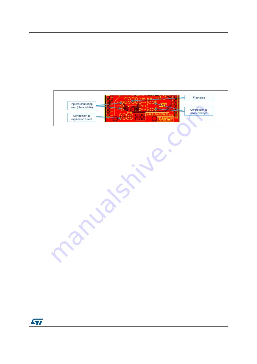
8 Prototyping
area
A prototyping area has been implemented in order to perform small additional
configurations.
It allows the user to connect an expansion board, components on input and output, and a
divider bridge for a 5 V to 3.3 V conversion, as shown on the following figure.
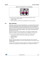
Figure 11. Prototyping area
Note also that the supply voltage of the operational amplifier can be either external or based
on the internal 3.3 V. If a high output voltage and thus a higher power supply voltage is
required, it is recommended to place jumper JP3 in the V
ext
position.


