Instrumentation amplifier configuration
UM1955
4/28
DocID028405 Rev 1
1 Instrumentation
amplifier
configuration
The instrumentation amplifier configuration allows you to amplify a differential signal without
impacting it thanks to the high impedance of operational amplifier input stage. Moreover,
with the high accuracy resistors, this configuration features high rejection to common mode
voltage.
1.1 Schematic
diagram
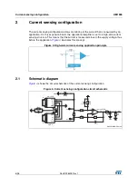
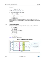
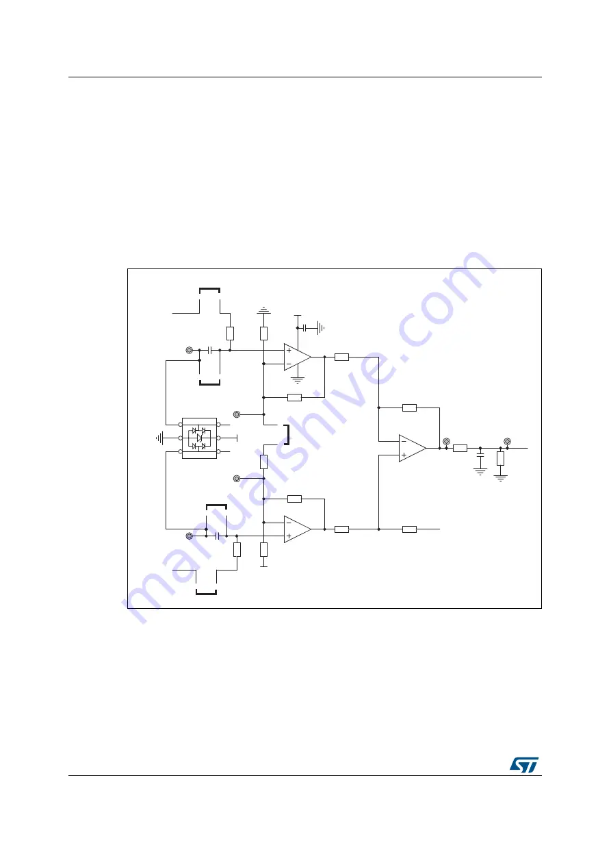
Figure 2
below depicts the circuit schematic of the instrumentation amplifier configuration.
Figure 2. Instrumentation amplifier configuration circuit schematic
1.2
How to set up the board
The instrumentation amplifier section of the expansion board includes several jumpers for
improved versatility. For this configuration, jumpers JP2, JP4 and JP5 must be mounted and
JP6 and JP7 should not be mounted. If the input signal is capacitive, a bias voltage needs to
be added. This configuration is possible by mounting jumpers JP6 and JP7. Once jumpers
have been set in the required configuration, the differential must be connected to pins Inst_n
and Inst_p.
9
9
76=,37 $
N
5
N
5
*1'
9
0
5
S)
&
1& 5
9
1& 5
*1'
$
9UHI
*1'
76=,37 &
76=,37 %
*1'
9UHI
9UHI
0
5
S)
&
N
5
N
5
N
5
N
5
Q)
&
N
5
N
5
S)
&
-3
-3
9
-3
-3
-3
,QVWBQ
5JDLQBD
5JDLQBE
,QVWBS
73
N
5J
9EXV
*1'
,2
,2
,2
,2
(6'
(6'$/&/6&
73
*1'
*63*',


