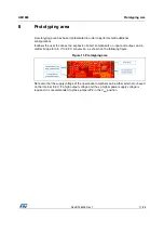
DocID028405 Rev 1
5/28
UM1955
Instrumentation amplifier configuration
28
1.3 Theoretical
output
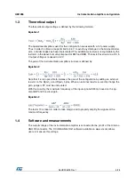
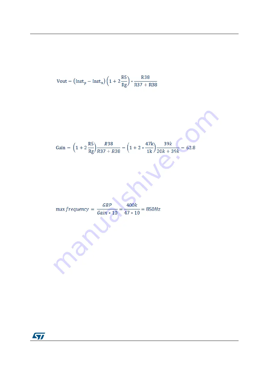
The theoretical output voltage is defined by the following formula:
Equation 1
The operational amplifiers used for this configuration are used with a 5 V power supply.
Thus in order to obtain a range limited to 3.3 V to avoid any damage on the microcontroller
side, a divider bridge has been implemented. This additional structure is recognizable by the
last term in the above formula (composed of R37 and R38). Thanks to this structure, a DC 5
V output voltage is reduced to 3.2 V.
The gain of this instrumentation amplifier structure is defined by:
Equation 2
Note that it is also possible to increase the gain of the configuration by adding an external
resistor on the Rgain_a and Rgain_b pins. When an external resistor is used to change the
gain, jumper JP2 must be unmounted.
With this circuitry, the maximum frequency of the input signal is 850 Hz based on the op-
amp GBP and the circuit gain.
Equation 3
The factor 10 is taken in order to take margin and to properly amplify the signals at the
maximum frequency.
1.4
Software and measurements
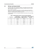
The output voltage of the instrumentation amplifier is connected to the pin A1 of the Arduino
UNO R3 connector. The X-CUBE-ANALOG1 software available on www.st.com allows
users to measure this voltage.


