DocID028405 Rev 1
7/28
UM1955
Current sensing configuration
28
2.2
How to set up the board
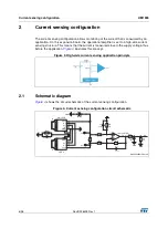
With this expansion board, users can measure the current of a USB-powered device or any
5 V application. It is important not to go beyond 5 V in order to avoid operational amplifier
damage. To help protect the circuit, an ESDAULC6-1U2 unidirectional ESD protection
device has been implemented.
Monitoring USB-powered device current: connect the charger (wall adapter or PC) to the
Micro-USB port. Then connect the bottom USB port to the required device.
Monitoring other application current: it is also possible to measure the current of
applications that are not USB powered. The power supply voltage should be connected to
I
in
, and I
out
should be connected to the power supply voltage pin of the application.
2.3 Theoretical
output
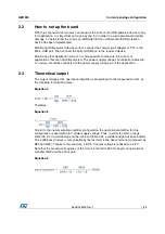
The output voltage of the operational amplifier is proportional to the measured current, as
the following formula illustrates:
Equation 4
Therefore,
Equation 5
Similar to the instrumentation amplifier configuration, the operational amplifier for this
configuration is used with a 5 V power supply voltage. Thus, in order to obtain a range
limited to 3.3 V avoid damage on the microcontroller side, a divider bridge has been added.
This additional structure is recognizable by the last term in the above formula (composed by
R30 and R39). Thanks to this structure, a DC 5 V output voltage is reduced to a 3.2 V.
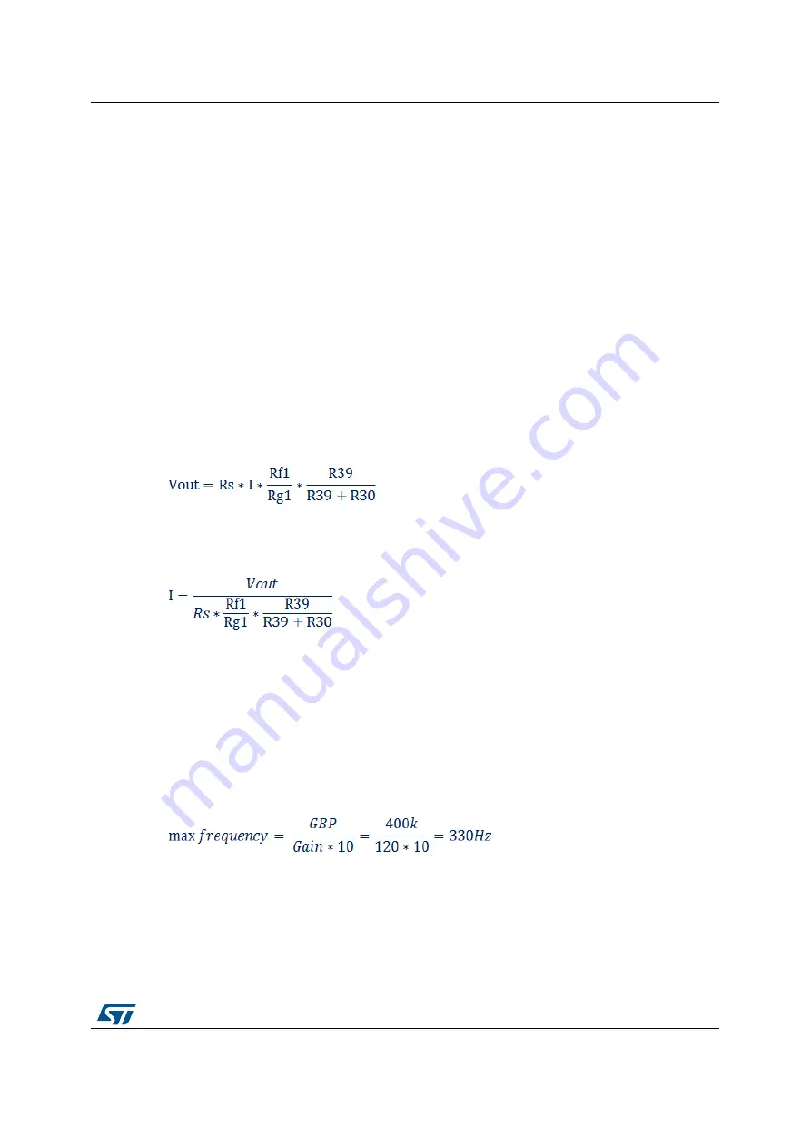
Note that the maximum frequency of this circuit is limited to 330 Hz based on operational
amplifier GBP and the circuit gain.
Equation 6


