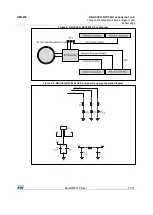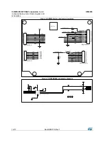
Hardware description
and configuration
UM2235
8/17
DocID030718 Rev 1
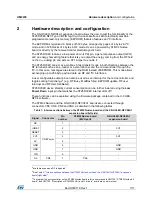
Signal
Connector
Pin
number
STM32 Nucleo board
(MCU port)
X-NUCLEO-NFC04A1
expansion board
A1
Analog
2
PA1
-
A2
3
PA4
-
A3
4
PB0
-
A4
5
PC1/PB9
(1)
-
A5
6
PC0/PB8
(1)
-
Notes:
(1
)
Acting on the STM32 Nucleo board solder bridge.
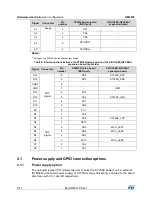
Table 2: Interconnections between the STM32 Nucleo board and the X-NUCLEO-NFC04A1
expansion board (right side)
Signal
Connector
Pin
number
STM32 Nucleo board
(MCU port)
X-NUCLEO-NFC04A1
expansion board
D15
CN5
Digital
10
PB8
ST25DV_SCL
D14
9
PB9
ST25DV_SDA
AREF
8
-
-
GND
7
-
GND
D13
6
PA5
-
D12
5
PA6
ST25DV_GPO
D11
4
PA7
-
D10
3
PB6
-
D9
2
PC7
-
D8
1
PA9
-
D7
CN9
Digital
8
PA8
ST25DV_LPD
D6
7
PB10
-
D5
6
PB4
MCU_LED1
D4
5
PB5
MCU_LED2
D3
4
PB3
-
D2
3
PA10
MCU_LED3
D1
2
PA2
-
D0
1
PA3
-
2.1
Power supply and GPIO connection options
2.1.1
Power supply option
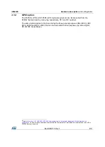
The on-board jumper (ST1) allows the user to select the ST25DV power source: external
(STM32 Nucleo board power supply) or ST25DV energy harvesting, indicated on the board
silkscreen with 3.3 V and EH respectively.


