background image

ELECTRICAL

Ground motor before connecting to electrical power supply. Failure to

ground motor can cause severe or fatal electrical shock 
hazard.

Do not ground to a gas supply line.

To avoid dangerous or fatal electrical shock, turn OFF power to motor

before working on electrical connections.

Ground Fault Circuit Interrupter (GFCI) tripping indicates an electrical

problem. If GFCI trips and will not reset, have a qualified 

electrician inspect and repair electrical system.

Exactly match supply voltage to nameplate voltage! Incorrect voltage

can cause fire or seriously damage motor and voids warranty. 
If in doubt consult a licensed electrician.

Voltage:

Voltage at motor must be not more than 10% above or below motor nameplate
rated voltage or motor may overheat, causing overload tripping and reduced
component life. If voltage is less than 90% or more than 110% of rated voltage
when motor is running at full load, consult power company.

Grounding/Bonding:

Install, ground, bond and wire motor according to local or National Electrical
Code requirements.
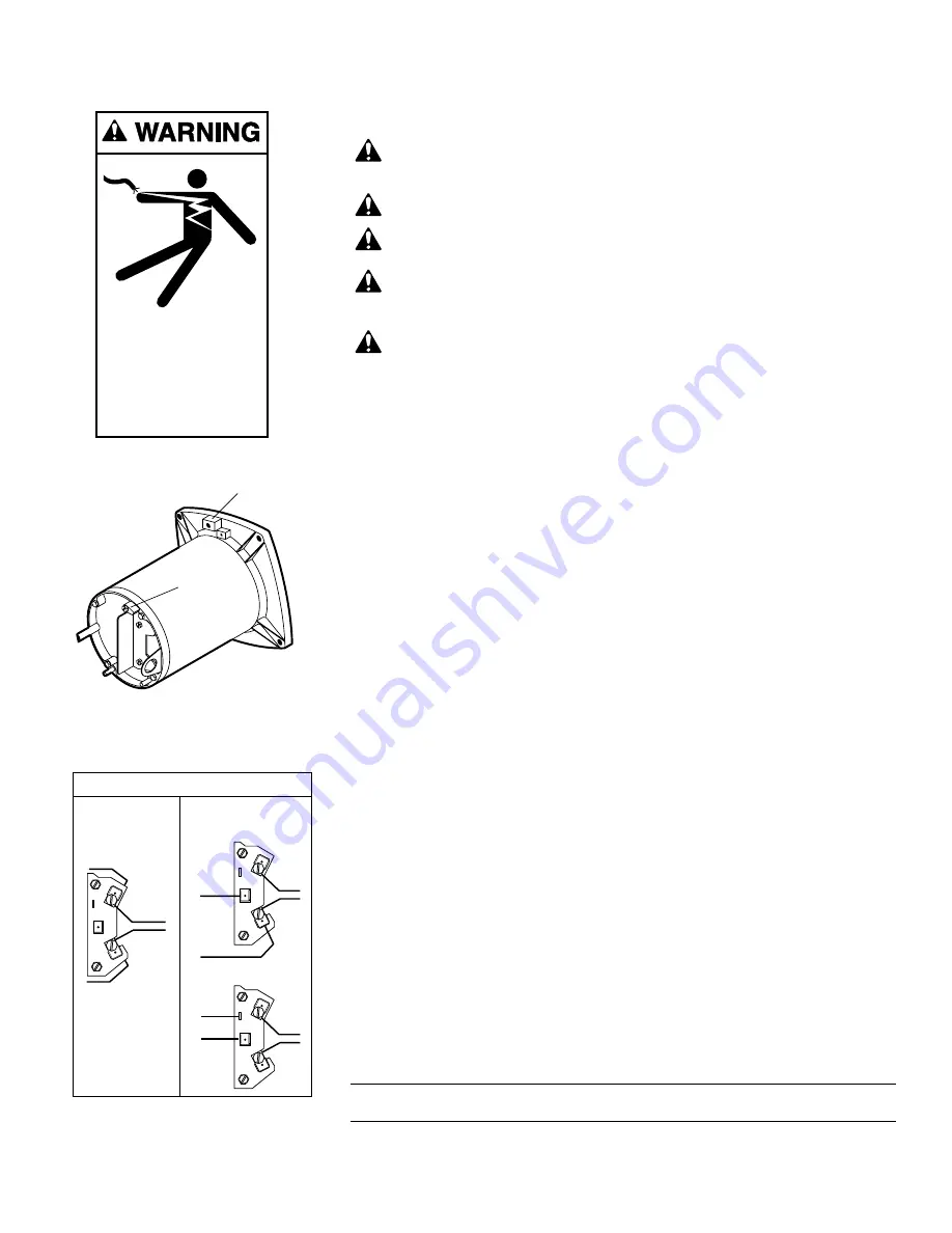
Permanently ground motor. Use green ground terminal provided under motor
canopy or access plate (See Figure 3A); use size and type wire required by
code. Connect motor ground terminal to electrical service ground.
Connect a No. 8 AWG (8.4 sq. mm) solid copper bonding wire to the pressure
wire connector provided on the motor housing and to all metal parts of the
swimming pool, spa, or hot tub and to all electrical equipment, metal piping or
conduit within 5 feet (1.5m) of the inside walls of swimming pool, spa, or hot
tub.

Wiring (See Figure 3B):

Pump must be permanently connected to circuit. Table I, Page 6, gives correct
wire and circuit breaker sizes for the pump alone. If other lights or appliances
are also on the same circuit, be sure to add their amp loads to pump amp load
before figuring wire and circuit breaker sizes. (If unsure how to do this or if this
is confusing, consult a licensed electrician.) Use the load circuit breaker as the
master on-off switch.
Install a Ground Fault Circuit Interrupter (GFCI) in circuit; it will sense a short-
circuit to ground and disconnect power before it becomes dangerous to pool
users. For size of GFCI required and test procedures for GFCI, see manufactur-
er’s instruction.
In case of power outage, check GFCI for tripping (which will prevent normal
pump operation). Reset if necessary. 

NOTICE: 

If you do not use conduit when wiring motor, 

be sure

to seal wire

opening on end of motor to prevent dirt, bugs, etc., from entering.

6

BONDING

LUG

GREEN 

GROUND 

SCREW

Hazardous voltage.
Can shock, burn,
or cause death.

Ground pump before
connecting to
power supply.

FIGURE 3A: Typical ground screw
and bonding lug locations

White 

230
Volt
Lines

A

B

L2

L1

Blue

SINGLE

VOLTAGE

MOTORS

DUAL

VOLTAGE

MOTORS

A

B

L2

L1

White
w/Black 
Tracer

Black

115
Volt
Lines

A

B

L2

L1

White
w/Black 
Tracer

Black

230
Volt
Lines

Motor Terminal Board Connections

FIGURE 3B: Wiring connection 
diagram

TABLE I - RECOMMENDED FUSING AND WIRING DATA

Dist. in Ft. (m) (Serv. to Motor)

Motor

Branch Fuse

Max Load

Voltage/

0-100’

101-200’

201-300’

H.P.

Rating Amps*

Amps

Hz/Phase

(0-30)

(31-60)

(61-90)

1/2

20

13.4

115/60/1

12 (3)

10 (5.5)

8 (8.4)

1/2

15

6.7

230/60/1

14 (2)

14 (2)

14 (2)

*Time delay fuses are recommended instead of standard fuses in any motor circuit.

Summary of Contents for 1/2 HP

Page 1: ...Pool Spa Group 293 Wright Street Delavan WI 53115 International 262 728 5551 FAX 262 728 7550 www starite com Union City TN Delavan WI Mississauga Ont Murrieta CA 2004 Sta Rite Industries Printed in U S A S44 Rev 4 5 04 This manual should be furnished to the end user of this pump its use will reduce service calls and chance of injury and will lengthen pump life ...

Page 2: ... CAREFULLY The Sta Rite PLB Series Booster pump Is designed for use with automatic swimming pool cleaning systems Is an excellent performer durable reliable Table of Contents Safety Instructions 3 Installation 4 5 Electrical 6 Operation 7 Storage Winterizing 7 Pump Service 8 9 Repair Parts List 10 Troubleshooting Guide 11 Warranty 12 ...

Page 3: ...ty checks Check all clamps bolts lids and system accessories before testing Release all air in system before testing Tighten Sta Rite trap lids to 30 ft lbs 4 1 kg m torque for testing Water pressure for test must be less than 25 PSI 7 5 kg cm2 Water Temperature for test must be less than 100o F 38o C Limit test to 24 hours After test visually check system to be sure it is ready for operation Remo...

Page 4: ...nstall pump and wiring Pump mount must Be solid Level Rigid Vibration free To reduce vibration and pipe stress bolt pump to mount Allow pump suction inlet to be as close to pool return line as possible Allow use of short direct suction pipe from tee on return line See Fig 1 Allow for gate valves in suction and discharge piping Have adequate floor drainage to prevent flooding Be protected from exce...

Page 5: ...discharge pipes independently Place these supports near the pump To avoid a strain left by a gap at the last connection start all piping at the pump and run pipe away from the pump To avoid airlocking slope suction pipe slightly upward toward the pump NOTICE To prevent flooding when removing pump for service all flood ed suction systems must have gate valves in suction and discharge pipes Fittings...

Page 6: ...swimming pool spa or hot tub Wiring See Figure 3B Pump must be permanently connected to circuit Table I Page 6 gives correct wire and circuit breaker sizes for the pump alone If other lights or appliances are also on the same circuit be sure to add their amp loads to pump amp load before figuring wire and circuit breaker sizes If unsure how to do this or if this is confusing consult a licensed ele...

Page 7: ...oblems do not cover pump with plastic For outdoor unprotected installations 1 Enclose entire system in a weatherproof enclosure 2 To avoid condensation corrosion damage allow ventilation do not wrap system in plastic 3 Use a 40 propylene glycol 60 water solution to protect pump to 50 F Draining Pump 1 Pump down water level below all inlets to the pool To avoid dangerous or fatal electrical shock h...

Page 8: ...user Figure 5 5 If impeller must be replaced loosen two machine screws and remove motor canopy see Figure 6 6 Capacitor voltage may be hazardous To discharge capaci tor hold insulated handle screwdriver BY THE HANDLE and short capaci tor terminals together see Figure 6 Do not touch metal screwdriver blade or capacitor terminals If in doubt consult a qualified electrician 7 Unscrew capacitor clamp ...

Page 9: ...right side up 8 Apply liquid soap sparingly one drop is sufficient to inside diameter of rotating seal member 9 Slide rotating seal member carbon face first onto shaft until rubber drive ring hits shaft shoulder NOTICE Be sure not to nick or scratch carbon face of seal when pass ing it over threaded shaft end or shaft shoulder The carbon surface must remain clean or short seal life will result 10 ...

Page 10: ...al 1 17351 0102S 7 Impeller 1 J105 8PACN 8 Diffuser 1 J1 40P 9 Screw 8 32 x 7 8 Lg 5 U30 542SS 10 O Ring Diffuser 1 U9 199 11 Clamp Tank Body 1 C19 54SS 12 Reducer Bushing 1 U78 118PT 13 Tank Body Front Half 1 L76 37P 14 Pipe Plug 1 8 1 WC78 41T 15 Bushing 1 L23 4P1 15A Gasket 1 L20 40 16 Reducer Bushing 1 1 4 x 3 4 1 U78 123PT 17 Pipe Plug 1 1 U78 830PT 18 Pipe Plug 1 4 2 WC78 40T 19 Base 1 C4 42...

Page 11: ...eal Page 9 for reassembly 2 Impeller and diffuser may be worn If so order replacement parts from Repair Parts List Page 10 Electrical 1 Pump may be running too slowly check voltage at motor terminals and at meter while pump is running If low see wiring instructions or consult power company Check for loose connections 2 Pump may be too hot A Check line voltage if less than 90 or more than 110 of ra...

Page 12: ...er purchaser Purchaser only Sta Rite shall have the option to repair or replace the defective product at its sole discr tion Purchasers must pay all labor and shipping charges necessary to replace the product covered by this warranty Requests for warranty service must be made through the installing dealer This warranty shall not apply to any prod uct that has been subject to negligence misapplicat...

Reviews: