


3
PIPING - GENERAL
Support both suction and discharge piping independently at a
point near the pump to avoid putting a strain on the pump
housing. Start all piping
AT THE PUMP.
Increase pipe diameter at both the suction and discharge by
one (1) standard pipe size (minimum) to obtain desired per-
formance and flow rate. Refer to Table I when sizing pipe for
your pumping system.
NOTE:
Do not use pipe with
smaller
diameter on the suction
side of pump.
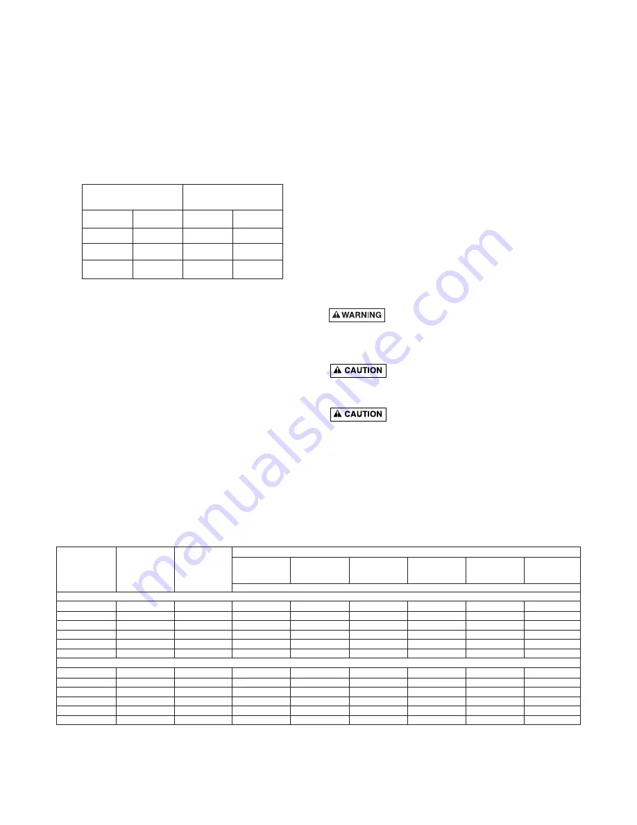
TABLE I
Pipe Tapping
Recommended
Size On Pump
Pipe Size
Suction
Discharge
Suction Discharge
1-1/4
1
1-1/2
1-1/4
1-1/2
1-1/4
2
1-1/2
2
1-1/2
3
2
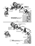
SUCTION PIPE
Increase pipe size from pump tapping as shown in Table I.
Figure 1 (Page 2) depicts a recommended run of pipe and fit-
tings for the suction side of a centrifugal pump. Please refer
to this illustration when choosing pipe and fittings for your
suction connection.
IMPORTANT:
All connections must be air tight!
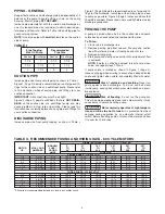
Figure 2 (Page 2) depicts conditions that are
NOT DESIR-
ABLE
on the suction side of a centrifugal pump and may
cause problems in flow rate and priming. Please look this
illustration over carefully before choosing pipe and fittings for
your suction connection.
DISCHARGE PIPING
Increase pipe size from pump tapping as show in Table I.
Figure 1 (Page 2) depicts a recommended run of pipe and fit-
tings for the discharge. Install tee with priming plug as close
to pump as possible. Figure 2 (Page 2) notes conditions that
should be avoided. Please read over carefully before making
discharge connection.
PRIMING THE PUMP
A pump is primed when all air in the suction line and pump
volute has been evacuated and replaced with water.
To Prime:
1. Close valve in discharge line.
2. Remove priming plug from tee and fill pump and suction
line with water until water is flowing back out of tee.
3. Replace priming plug.
4. Start pump and slowly open valve until desired water flow
is achieved.
NOTE:
If water is not being pumped, turn off pump, close
valve, and repeat steps 1 thru 4.
If pump volute is rotated as shown in Figure 1 (Page 2),
loosen vent plug when priming to evacuate air trapped inside
volute and tighten when volute is completely filled with water.
Risk of explosion and scalding
. Never run
pump against closed discharge. To do so can boil water
inside pump, causing hazardous pressure buildup and possi-
ble explosion.
Risk of flooding
. Do not run the pump dry.
This will damage mechanical seal and void warranty. It may
cause burns to person handling pump.
Motor normally operates at high tempera-
ture and will be too hot to touch.
It is protected from heat
damage during operation by an automatic internal cutoff
switch. Before handling pump or motor, stop motor and allow
it to cool for 20 minutes.
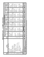
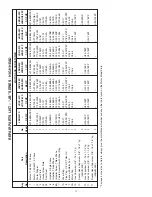
TABLE II - RECOMMENDED FUSING AND WIRING DATA - 60 CYCLE MOTORS
DIAMETER IN FEET FROM MOTOR TO METER
BRANCH
0’
51’
101’
201’
301’
401’
MOTOR
MAX. LOAD
FUSE*
TO
TO
TO
TO
TO
TO
HP
AMPERES
RATING
50’
100’
200’
300’
400’
500’
AMPS
WIRE SIZE
SINGLE PHASE - 115/230 VOLT
1/3
9.4/4.7
15/15
14/14
14/14
10/14
10/14
6/14
6/12
1/2
9.4/4.7
15/15
14/14
14/14
10/14
10/14
6/14
6/12
3/4
12.2/6.1
20/15
12/14
12/14
10/14
8/14
6/12
6/12
1
14.8/7.4
20/15
12/14
12/14
8/14
6/14
6/12
4/10
1-1/2
19.2/9.6
25/15
10/14
10/14
8/14
6/12
4/10
4/10
2
24.0/12.0
30/15
12/14
10/14
6/14
6/12
4/10
4/10
THREE PHASE - 230/460 VOLT
1/2
2.3/1.15
15/15
14/14
14/14
14/14
14/14
14/14
14/14
3/4
3.1/1.55
15/15
14/14
14/14
14/14
14/14
14/14
14/14
1
3.6/1.8
15/15
14/14
14/14
14/14
14/14
14/14
14/14
1-1/2
4.7/2.35
15/15
14/14
14/14
14/14
14/14
14/14
14/14
2
6.8/3.4
15/15
14/14
14/14
14/14
14/14
12/14
12/14
2-1/2
8.5/4.25
15/15
14/14
14/14
14/14
14/14
12/14
10/14
*A Fusetron is recommended instead of a fuse in any motor circuit.


