40024-0707
1 12
R
Home Security Cabinet
Installation Instructions
®
Key #:
Serial #:
IMPORTANT:
Record the serial and key numbers from the back of the
cabinet. You will need the serial number information in
order to replace lost keys.
Do not store this document in your security cabinet.
Keep keys in a secure place away from children.
NOTE:
Assemble shelving and barrel rests before
mounting the cabinet to a wall or floor. Exterior access
is required for assembling these items. Review these
instructions prior to installation.
MODEL GC-14P
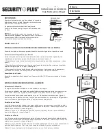
INSTALLATION OF BARREL RESTS AND SHELF
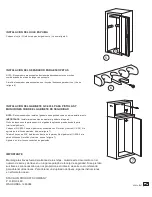
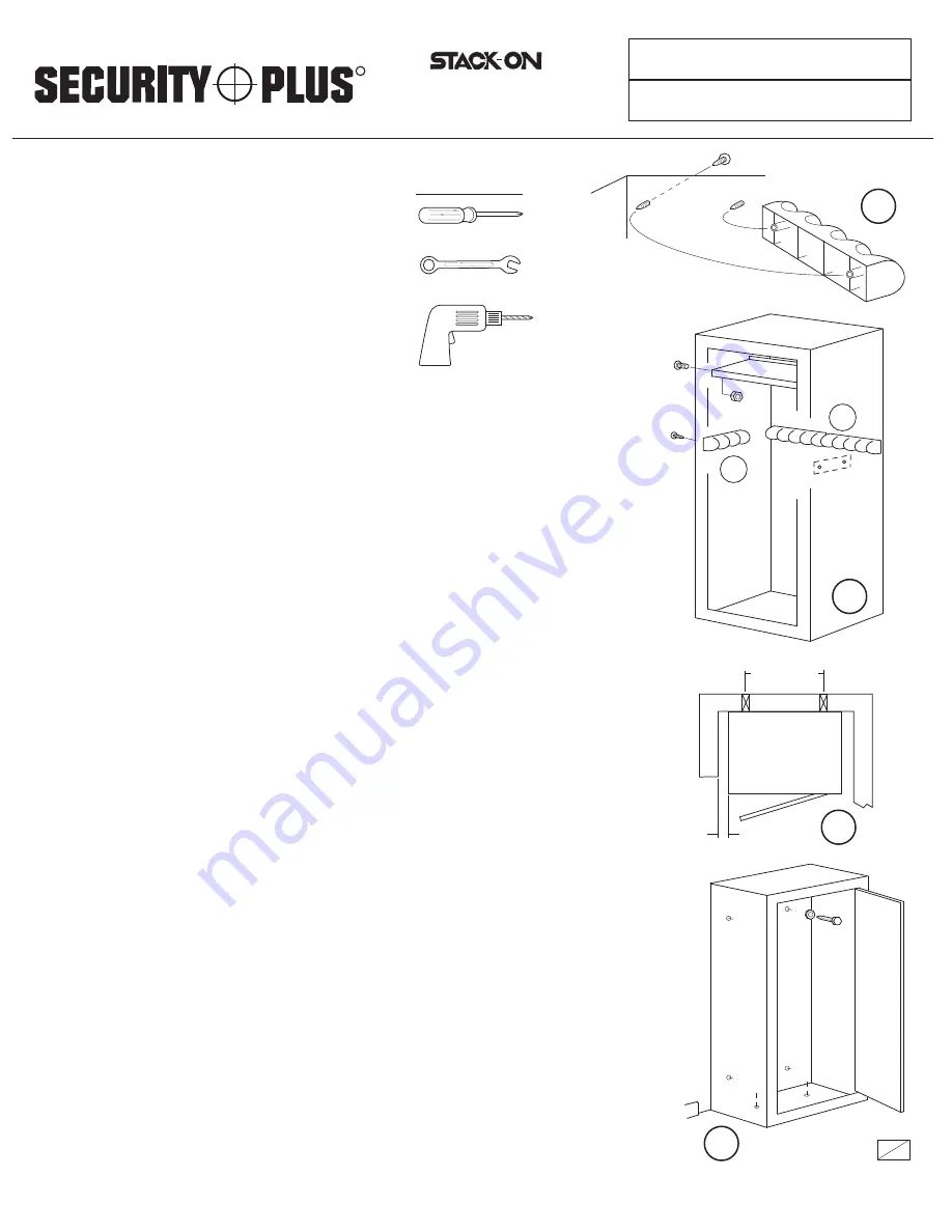
Assemble shelving and barrel rests before mounting the cabinet to a wall or floor.
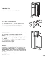
Barrel rest assembly
Install the 4-position barrel rests (A) to the back of the cabinet and the 3-position barrel rests (B) to the
sides of the cabinet as shown in figure 2.
1. Thread the screws into the pilot holes from the outside of the cabinet. (See figure 1)
2. Align the holes of the barrel rest over the tips of the screws and lightly press the barrel rest into place.
(See figure 1)
3. Now tighten the screws from the outside of the cabinet. Tighten each screw partially, alternating from
one screw to the other until they are both tight. Do not over tighten.
Shelf assembly
Assemble the shelf inside the cabinet with (4) 10-32 nuts and bolts as shown in figure 2.
A
B
2
CABINET MOUNTING INSTRUCTIONS
Selecting a Location
Your Security Cabinet should be installed in an isolated, dry and secure area.
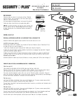
For greater security the cabinet must be fastened to a solid surface with a minimum space on either side.
Ideally the cabinet would be installed on the side wall of a closet. (See figure 3)
The cabinet should be flat against the wall and floor. Remove the baseboard if necessary. (See figure 4)
Insert the plastic plugs in the cabinet's top mounting holes if you are not installing the Pistol-Ammo cabinet
on the top of the security cabinet.
Wall Mount Option
The (4) mounting holes in the rear of the cabinet must line up with the 16" centers of the wall studs. Drill
new holes in the cabinet if necessary. (See figure 4)
Drill (4) 3/16" pilot holes into the wall studs and secure the cabinet to the wall using (4 ea.) lag bolts and
washers. (See figure 4)
Floor Mount Option
The (4) mounting holes in the rear of the cabinet must line up with the 16" centers of the wall studs. Drill
new holes if necessary. (See figure 4)
Drill (2) 3/16" pilot holes into the wall studs lining up with the top (2) mounting holes in the back of the
cabinet. Secure the cabinet to the wall using (2) lag bolts and washers.
Drill (2) pilot holes and secure the cabinet bottom to the floor with (2) lag bolts and washers.
3
16"
CENTERS
CABINET
TOP VIEW
MINIMUM
4
7/16" wrench
Phillips screwdriver
Drill with
3/16" bit
Tools Required:
1


