

Page | 6
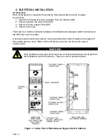
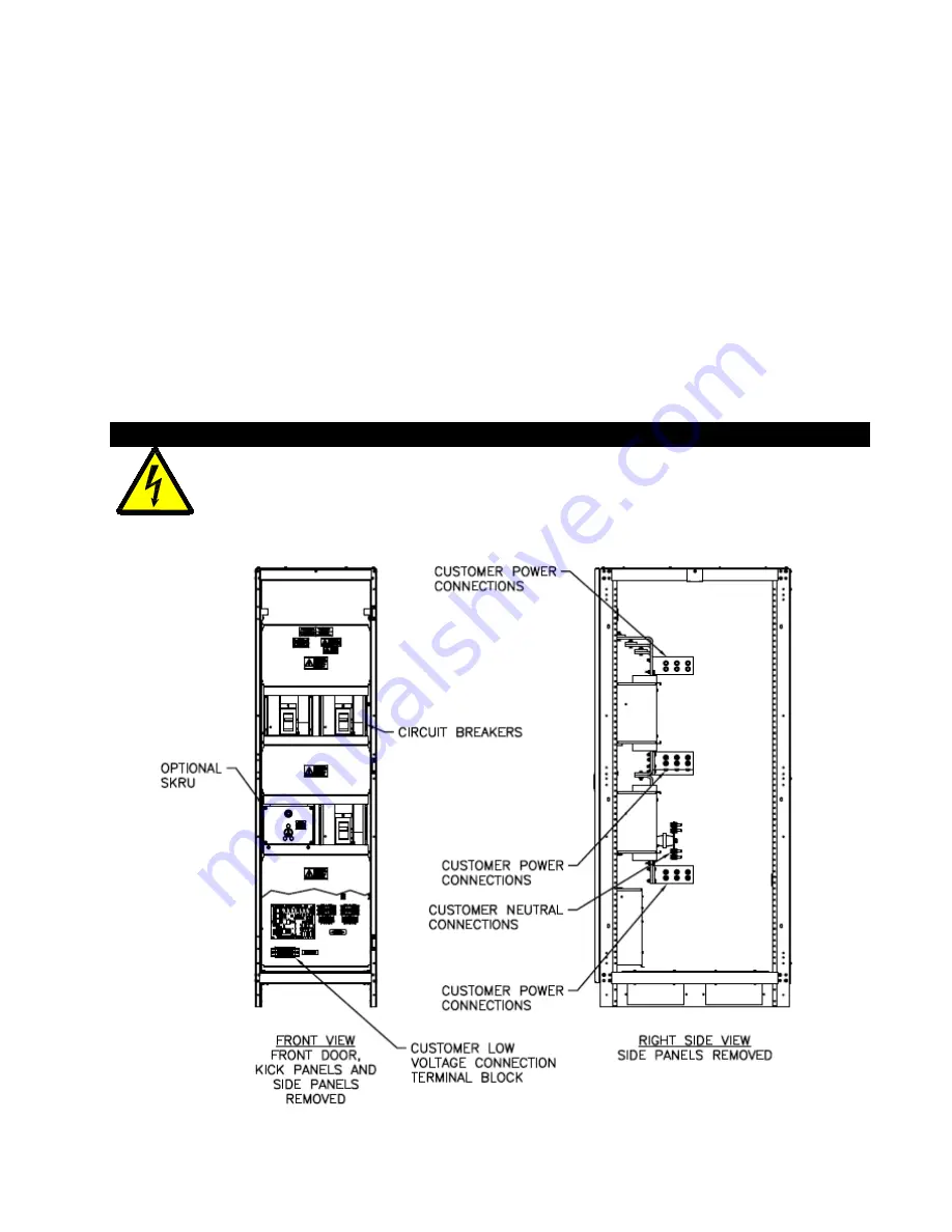
4. ELECTRICAL INSTALLATION
4.1 Overview
Each of the pieces of equipment covered by this manual has four sets of power
connections:
1. Input from the power source, typically, from the electric utility.
2. Power routed to the input of the UPS.
3. Power from the output of the UPS.
4. Power to the load
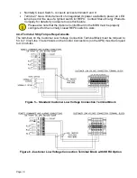
There are four control connections between the Maintenance Bypass Switch Cabinet and
the UPS that must be made.
A user accessible disconnect device must be provided (by other’s) between the output of
this cabinet and the load. Refer to Error! Reference source not found. for current
requirements.
WARNING
Only qualified service personnel (such as a licensed electrician) should perform
the installation and initial startup. There is a risk of electrical shock.
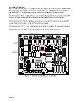
Figure 3 - Inside View of Maintenance Bypass Switch Cabinet