Page | 11
5. OPERATION
Refer to the User's Manual for the UPS for instructions on operating the UPS part of the
system.
If the UPS is part of a parallel system, special operating instructions apply.
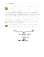
5.1 Maintenance Bypass Switch (MBS)
The purpose of the Maintenance Bypass Switch (MBS) is to facilitate servicing the UPS
without removing power from the load. The main functional components of the MBS are
three circuit breakers that are used as disconnect switches. The breakers each have three
positions: off (down), on (up), and tripped (in between off and on). If a breaker will not reset
or trips as being turned on, backfeed prevention interlock is active and the proper
conditions (as described below) will have to be present before the breaker can be operated.
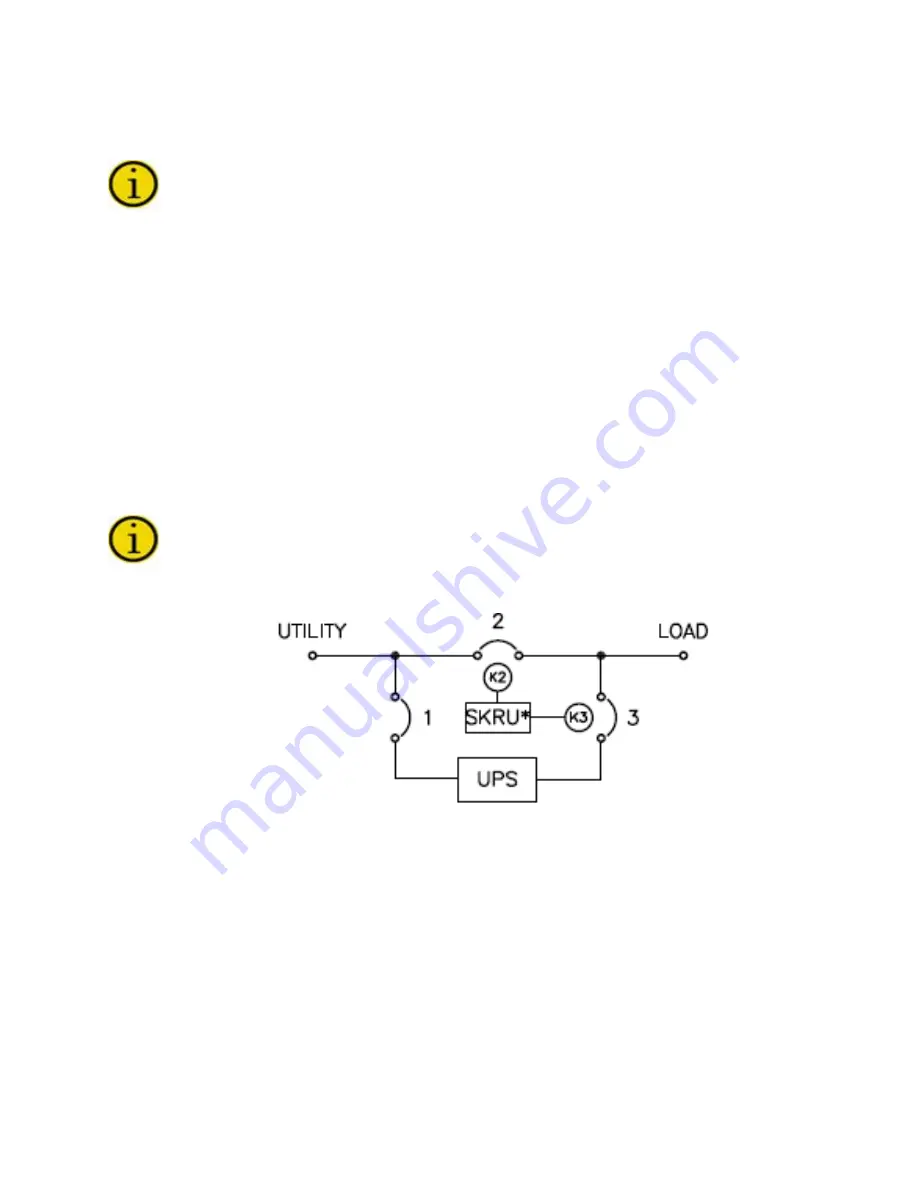
BKR1 supplies power from the supply (utility) to the bypass input of the UPS. For single
input UPS configurations, it also supplies power to the rectifier input.
BKR2 bypasses the path through BKR1, the UPS, and BKR3 and connects the supply
directly to the load.
BKR3 connects the output of the UPS to the load.
BKR2 and BKR3 must never be closed at the same time unless the UPS is in
bypass mode. Control signals support an interlock function to prevent BKR2 from
being closed unless BKR3 is open or the UPS is in bypass mode.
*Optional
Figure 8 – System 1-line


