Page | 14
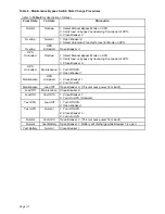
Common MBS operations: (refer to the UPS manual for UPS operations; BKR1,
BKR2, BKR3 are part of the Maintenance Bypass Switch Cabinet; all other switches
are part of the UPS)
To transfer from normal mode on the UPS to maintenance bypass—
1. Verify that the bypass source is satisfactory: at minimum, verify that the bypass
source lamp (LED1 at upper left) on the front panel of the UPS is steady green and
that the legend “BYPASS VOLTAGE FAIL” is not present on the display. If the load
is already being supported by the Static Bypass, the yellow “Load on Bypass” lamp
(LED4, upper right) will be steady (or flashing if the load exceeds the UPS rating).
Refer to Section 6 of the UPS manual regarding the indicators.
2. Close SWMB on the UPS. After SWMB is closed, the yellow “Load on Bypass” lamp
will flash and the inverter will stop and battery supported operation is no longer
possible.
3. Close BKR2.
4. Open BKR3.
5. Shut down the UPS, if desired, by opening SWOUT, SWIN, SWBY, and open the
Battery Disconnect(s). Optionally open SWMB.
6. If the UPS is shut down, open BKR1. The UPS is completely de-energized at this
point.
To transfer from MBS to normal mode—
1. Close BKR1.
2. On the UPS, verify that SWMB is closed, if not, close it.
3. Close SWBY, SWIN, and SWOUT. Wait 5 seconds.
4. Close BKR3.
5. Open BKR2.
6. Open SWMB. The UPS should start and operate normally.
7. When the display no longer shows: “Wait: DO NOT connect the BATTERY”, the
disconnect breakers in each battery cabinet should be closed. Refer to Section 4.6
for the proper procedure for connecting the battery.
Normal start-up
with load unpowered—
1. Verify that BKR2 is open; open it if closed.
2. Verify that SWBY is open.
3. Close BKR1 and BKR3.
4. Perform a normal UPS start-up as per Section 4.6 of the UPS manual.


