background image


Form No. 003-2282 Rev G 


2.1.10 Providing four different working modes, such as Normal, ECO, CF50 
and CF60, it may widely be used in a variety of applications. 


2.1.11 DC-start function allows the UPS to be started during power outages. 


2.1.12 Revolutionary battery management circuit analyzes battery 
discharging status to adjust battery cut-off point and extend the life of 
batteries. 


2.1.13 Intelligent temperature-controlled fan extends the life of the fan and 
reduces noise. 


2.1.14 Built in diagnostics use fault codes, displayed on the LCD, to assist in 
finding the cause of a problem with the unit. 


2.1.15 In case the UPS is out of order, Fault status will be shown on the LCD 
screen.   


2.1.16  When the UPS is operated as a frequency converter under CF50 or 

CF60 mode, the recommended load connected shall be 75% of rated 
capacity if the input voltage is between 176~280Vac and 50% of the 
rated capacity if the input voltage is 160~280Vac.   

Summary of Contents for SC11021T

Page 1: ...Ohio 45403 U S Toll Free 866 261 1191 937 253 1191 Fax 937 253 1723 Web site www stacoenergy com UniStar P Series 6kVA 8kVA 10kVA Parallel Redundancy Capacity On Line UPS User s Manual Tower Models S...

Page 2: ...tallation of Casters Cover 15 3 4 Terminal Block Explanation 16 3 5 Operation Test and Installation Instruction 19 4 Troubleshooting Guide 32 4 1 Trouble Shooting 32 5 Bundled Software Installation Gu...

Page 3: ...AC input is available there will be voltage at the output terminals 1 1 5 Make sure that the AC Utility power source is correctly grounded 1 1 6 Do not open the case as there are no serviceable parts...

Page 4: ...rranty will be null and void When installed and being used the batteries will be automatically recharged and kept in top condition 1 1 19 This UPS supports electronic equipment in offices telecommunic...

Page 5: ...ended for Installation in a Controlled Environment 1 1 27 CAUTION 6Kva A load disconnect switch shall be provided by others for the AC output circuit To reduce the risk of fire connect only to a circu...

Page 6: ...ng is between 105 150 of rating At 150 of rating it switches to bypass mode immediately The UPS will automatically switch the load back to inverter mode once the overload condition ceases 2 1 5 If a s...

Page 7: ...fe of batteries 2 1 13 Intelligent temperature controlled fan extends the life of the fan and reduces noise 2 1 14 Built in diagnostics use fault codes displayed on the LCD to assist in finding the ca...

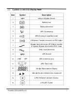
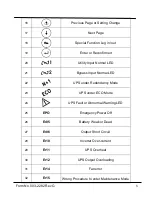
Page 8: ...Working in specified mode 6 A Blackout Transfer occurred in UPS Output 7 Bypass Input Abnormal UPS fails to transfer to bypass Bypass Abnormal at ECO mode 8 Utility Input Abnormal 9 OFF UPS Shutoff 1...

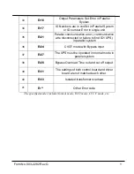
Page 9: ...ED 21 Bypass Input Normal LED 22 UPS under Redundancy Mode 23 UPS under ECO Mode 24 UPS Fault or Abnormal Warning LED 25 EPO Emergency Power Off 26 Er05 Battery Weak or Dead 27 Er06 Output Short Circu...

Page 10: ...disconnected or failure to find ID1 UPS in parallel system 36 Er24 CVCF mode with Bypass input 37 Er27 The UPS must be operated in normal mode in parallel system 38 Er28 Bypass Overload Time out and c...

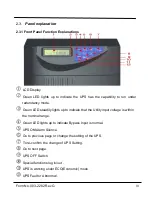
Page 11: ...reen LED steadily lights up to indicate that the Utility input voltage is within the nominal range Green LED lights up to indicate Bypass Input is normal UPS ON Alarm Silence Go to previous page or ch...

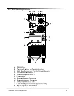
Page 12: ...r Parallel function C CAN Bus Connection Port for Parallel System D Customer Options Slot 1 E Customer Options Slot 2 F Cooling Fan G External Battery Connector H External Charger Connector I Utility...

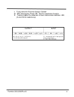
Page 13: ...o enable the function N Thermal breaker for protection of load in abnormal conditions CB3 8 and 10kVA models only OUTPUT INPUT G2 N22 L22 N21 L23 L21 G1 N1 L12 L11 N22 L22 N21 L23 L21 UPS OUTPUT L11 n...

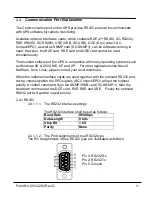
Page 14: ...2000 ME NT and XP For other applications like Novell NetWare Unix Linux please contact your local distributor When the optional interface cards are used together with the onboard RS232 port during com...

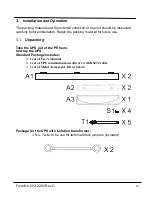
Page 15: ...ation Retain the packing material for future use 3 1 Unpacking Take the UPS out of the PE foam Unwrap the UPS Standard Package includes 1 set of User s Manual 1 set of UPS communication software with...

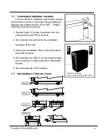
Page 16: ...below 1 Keep at least 12 inches clearance from the rear panel of the UPS to the wall 2 Do not block the air flow to the ventilation openings of the unit 3 Check the installation site to avoid excessi...

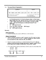
Page 17: ...G1 UPS Input Ground L21 L23 N21 L22 N22 UPS Output G2 UPS Output Ground Remarks Input Connection 1 Connect the utility AC source to UPS from L12 N1 terminal Output Connection s 2 When an Isolation tr...

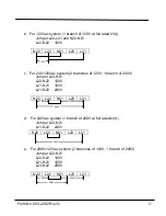
Page 18: ...ches of 120V 1 branch of 240V Jumper L22 N21 L22 N22 120V L21 N21 120V L21 N22 240V N22 L22 N21 L23 L21 120V 120V 240V d For 240Vac system 1 branch of 240V at full rated kVA Jumper L22 N21 L21 N22 240...

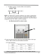
Page 19: ...internal connection of isolation transformer Consult the factory if voltage other than 120V 208V or 240V is necessary Use Mounting Cable Tie to attach cables 4 Power connections must be made using the...

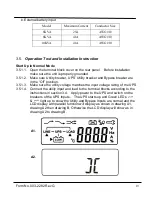
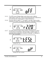
Page 20: ...atches the input voltage rating of the UPS 3 5 1 4 Connect the utility input and load to the terminal blocks according to the instructions in section 3 4 Apply power to the UPS and switch on the break...

Page 21: ...5 1 6 Press the UPS On Switch for approx 3 seconds then the alarm sounds twice and the LCD display changes from drawing B to drawing C C 3 5 1 7 The UPS performs another self test and the LCD display...

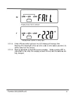
Page 22: ...should fail self test the LCD display will change from Drawing D to drawing E2 then an error code or error status section 2 2 will be shown on the screen 3 5 1 9 Start up operation of the UPS is now c...

Page 23: ...1 12 Within 15 seconds press the UPS On Switch again for about 3 seconds until the LCD display changes from drawing G to drawing H then the UPS will be in self test Mode The UPS will start the inverte...

Page 24: ...tility Input Drawing I1 Voltage from Bypass Input Drawing J Frequency from Utility Input Drawing K Frequency from Bypass Input Drawing L Inverter Output Voltage for units without isolation transformer...

Page 25: ...Form No 003 2282 Rev G 24 L Display shows the Inverter output Voltage M Display shows the UPS output frequency N Display shows the UPS output load level O Display shows the Battery Voltage...

Page 26: ...Inner Temperature UPS Default Data and Special Function Execution 3 5 1 15 After the UPS completely starts up press key pad to change the LCD display screen to drawing Q1 Q1 Display shows alarm b for...

Page 27: ...Windows Drawing T Output Frequency Synchronization Window Drawing U Inverter Output Voltage Drawing V1 UPS Operation Mode Drawing W Output Voltage Micro Tune Value Drawing X UPS Id Drawing Y Parallel...

Page 28: ...lay shows Frequency Window is 3Hz U Display shows inverter output voltage V1 Display shows the UPS is operating in normal mode V2 Display shows the UPS is operating in Eco mode V3 Display shows the UP...

Page 29: ...ay shows the UPS is in position No 1 in a parallel system 3 5 1 17 Press scroll up key pad to execute special functions The Functions include alarm buzzer ON as drawing Q1 or alarm buzzer OFF as drawi...

Page 30: ...Form No 003 2282 Rev G 29 Drawing E1 otherwise it will show as drawing E2 and an error message will appear at the same time...

Page 31: ...200Vac 208Vac 220Vac 230Vac or 240Vac 3 5 1 24 Drawing V1 V2 V3 and V4 show the operating modes of the UPS Alternatives are Normal Eco Economic mode fixed 50Hz Output or fixed 60Hz Output 3 5 1 25 Dra...

Page 32: ...sages recorded 3 5 1 33 2 Refer to Chapter 2 2 to trouble shoot the problem Otherwise consult your local distributor for service 3 5 1 33 3 Press Off key pad for 5 seconds and the alarm will sound twi...

Page 33: ...the CAM switch to INV mode Fasten the cover back into position and repeat 3 5 1 5 to 3 5 1 89 The UPS will switch back to inverter mode 3 5 1 42 CAUTION It is required to go through 3 5 1 38 first the...

Page 34: ...allel units must be same Please refer chapter 3 5 to set them again 7 Reconnect the RJ 45 wire or set a UPS with ID 1 8 When the UPS is on CVCF mode it is prohibited to have a bypass input You have to...

Page 35: ...to the UPS communication port 2 Connect the female connector of the RS232 cable to a dedicated RS232 port of the computer 3 For optional interface cards refer to Section 6 for installation 5 2 Softwar...

Page 36: ...please refer to Chapter 2 4 Installation Position slot1 CHA CN4 or slot 2 CHB CN5 Adapted flat cable cable A or cable B For installation please refer to Chapter 0 6 3 RSE RS 485 P N SC RS485 CN1 allo...

Page 37: ...CHA CN3 or slot 2 CHB CN4 6 5 DCE Dry Contact B card P N SC Contact EPO The pin assignments of 10 Pin Terminal 1 2 3 4 5 6 7 8 9 10 Pin 1 UPS on Bypass mode Pin 2 Utility Normal Normal close contact...

Page 38: ...ion will be enabled in 1 minute after blackout occurs if the pin1 2 of both CN1 and CN6 be shorted by a jumper Or the shutdown function can only be enabled by pin 9 10 of CN3 if pin 2 3 of both CN1and...

Page 39: ...Form No 003 2282 Rev G 38 1 2 3 6 7 Installation of the Interface Cards...

Page 40: ...eplacement 1 Unscrew the bottom of the front panel as indicated below 2 Remove the front panel as indicated 3 Remove the screw of the battery pack fastener as shown 4 Remove the fastener as shown 5 Un...

Page 41: ...Form No 003 2282 Rev G 40 6 Turn the battery pack handle at 90 degree as shown 7 Remove the battery packs from the UPS as shown...

Page 42: ...RMS DIAGNOSTICS COMMUNICATIONS Status On LED LCD Line Mode Backup Mode ECO Mode Bypass Supply Battery Low Battery Bad Disconnected Overload Transferring with interruption UPS Fault Readings On LED LCD...

Page 43: ...TERY CABINETS Optional Model SC BP6000T 2 3 SC BP1100T 2 3 Type Sealed Lead Acid Maintenance Free 2 40 each 3 60 each 12V 9AH 240Vdc Sealed Lead Acid Maintenance Free 2 40 each 3 60 each 12V 9AH 240Vd...

Page 44: ...Form No 003 2282 Rev G 43 Staco Energy Products Co 301 Gaddis Blvd Dayton OH 45403 US Toll Free 866 261 1191 Fax 937 253 1723 www stacoenergy com...

Reviews: