www.ac.com.pl I info@ac.com.pl
www.ac.com.pl I info@ac.com.pl
AC S.A. ul. 42 Pułku Piechoty 50 I 15-181 Białystok, Poland I tel. +48 85 743 81 00, fax. +48 85 653 93 83
04.03.2021
Calibrating device kit for stroke setting
in the ACW01 and ACW02 injector rails
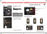
Calibrating device for injector stroke setting.
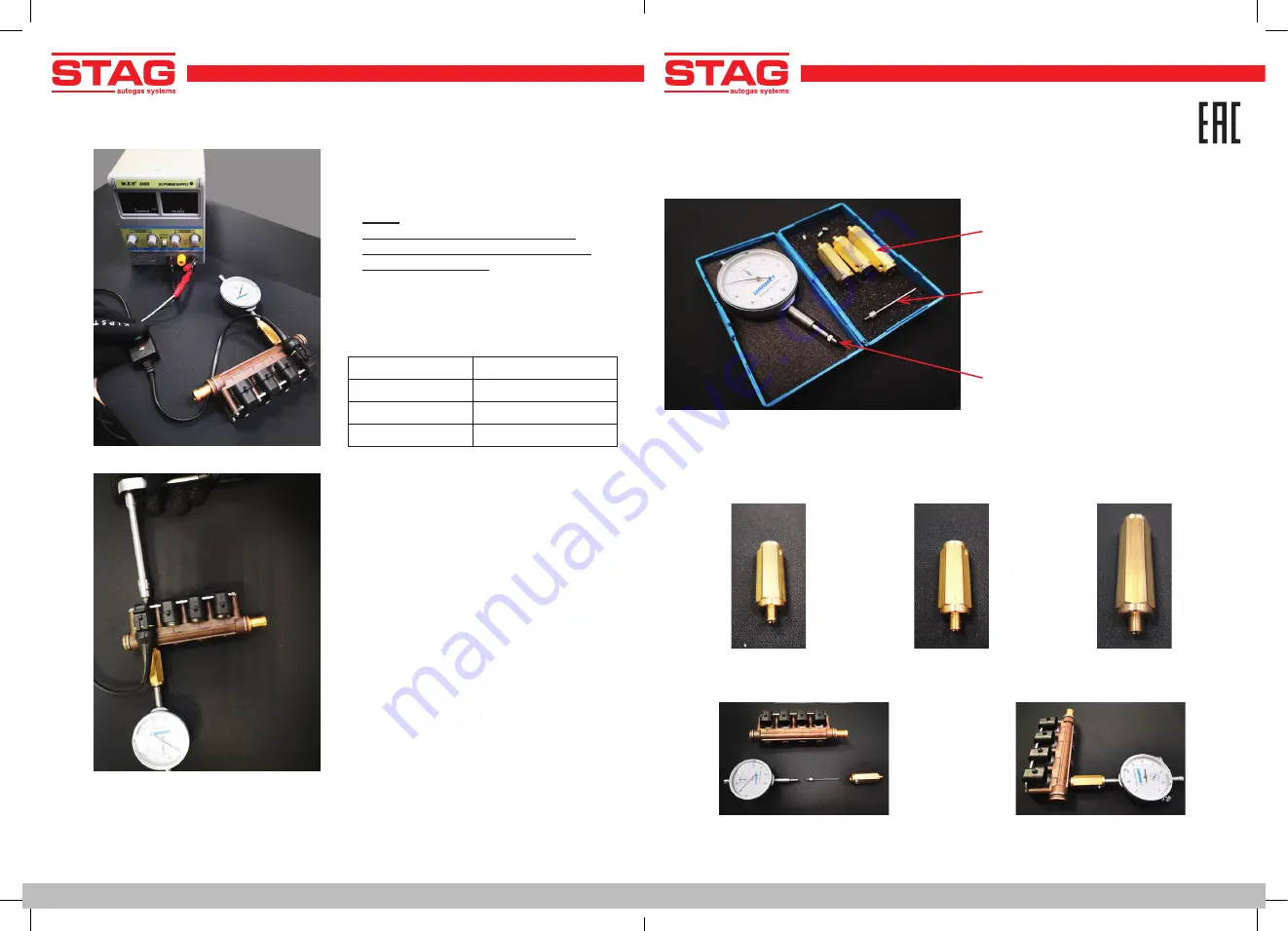
Calibrating device assembling
Fitting the relevant injector adapter
Assembly of the calibrating device
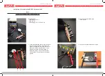
Connector body with adapter for injector
ACW01 / ACW02
Measuring pin
Dial gauge
Tighten the measuring spindle
to the clock sensor
Sign up for a clock sensor body
with a suitable adapter and tighten
the safety screw with the hex wrench No. 2
AC S.A. ul. 42 Pułku Piechoty 50 I 15-181 Białystok, Poland I tel. +48 85 743 81 00, fax. +48 85 653 93 83
ACW01
thread M6
ACW02
ACW01
thread M6x0,75
4. Press the button on the calibrating
device cable adapter and read the
plunger stroke.
Note:
holding down the button for more
than 4 seconds may lead to damage
of the injector coil!!!
5. If the readings are kept outside the
specified ranges, the stroke should be
corrected by screwing in (too large)
or screwing out (too small) the mounting
bracket.
6. After setting the stroke, repeat the above
procedure for other injector sections.
It should be properly:
ACW01 Standard: 0,50 mm +/- 0,01 mm
ACW01 BFC:
0,70 mm +/- 0,01 mm
ACW02 Standard: 0,50 mm +/- 0,01 mm
ACW02 BFC:
0,70 mm +/- 0,01 mm


