background image


04.05.     Einsiedler 

2007 

Isolating Repeater 

Type 9165/**-11-1* 


91 656 01 31 1 

none 

FM 

01 

15.04.11 


Reistle 


Kaiser 

Reistle 


22.10.12 


02 

 
Type 9165/**-11-1* 


Hazardous area: 

Class I, II, III; DIV 1; Group A-G or Class I; Zone 0; Group IIC/IIB Hazardous Locations 

Safe area:  


Non Hazardous; Division 2 or Zone 2 Hazardous (Classified) Locations 


The Isolating Repeater Type 9165/**-11-1* is an associated apparatus as well as a nonincendive apparatus for installation in non-
hazardous or Class I, Division 2 or Zone 2 Hazardous (Classified) Locations and provides intrinsically safe connections for one (or two) field 
devices located in Class I, II, III, Division 1, Group A-G or Class I, Zone 0 [AEx ia] Group IIC, hazardous locations according to NEC Article 
504/505 as listed below. 


Isolating Repeater Type 9165/ab-11-1f 

  a = numeral 1 or 2 for number of channels 
  b = numeral 1 or 6 for signal (without / with HART) 
   f = numeral 1 or 0 for special inputs (open- / short-circuit detection) 


Entity parameters for wiring configurations are as follows: 


L

o


L

o


C

o


C

o


V

OC 

[V] 

I

SC 

[mA] 

P

[mW] 

CL I, DIV 1, A,B / 

Zone 0, GP IIC 

CL I, DIV 1, C-G / 

Zone 0, GP IIB 

CL I, DIV 1, A,B / 

Zone 0, GP IIC 

CL I, DIV 1, C-G / 

Zone 0, GP IIB 

V

max


I

max


Type 9165/**-11-1* 

25.6 

96 

605 

1.9 mH 

11 mH 

103 nF 

800 nF 


Notes: 

1. 

For Connections refer to chapter Commissioning of Operating Instruction Id-No. 91 656 12 31 0. 

2. 

Intrinsically safe apparatus may be switches, thermocouples, LEDs, RTDs or an FM Approved System or  
Entity device connected in accordance with the manufacturer´s installation instructions. 

3. 

For Entity concept use the appropriate parameters to ensure the following: 
 

V

t

  or  V

OC


  V

max   

C

o

, C

a


  C

i

 + C

leads 

P

o


  P

i


 I

t

  or   I

SC


I

max   


L

o


L

a


 L

i

 + L

leads


4. 

Electrical apparatus connected to an intrinsically safe system should not use or generate voltages > 250 V (U

max

). 

5. 

Installation should be in accordance with Article 504/505 of the National Electrical Code ANSI/NFPA 70 and  
ANSI/ISA RP 12.06.01. 

6. 

Installation in Canada should be in accordance with the Canadian Electrical Code, CSA C22.1, Part 1, Appendix F. 

7. 

Use a general purpose enclosure meeting the requirements of IEC 61010-1 for use in non-hazardous or  
Class I, Division 2, Hazardous (Classified) Locations. 

8. 

Use an FM Approved Dust-ignition proof enclosure appropriate for environmental protection  
in Class II, Division 1, Groups E, F and G; and Class III, Hazardous (Classified) Locations. 

9. 

These modules are to be mounted on DIN rail, DIN rail with pac-Bus (type 9194) or pac-Carrier (type 9195). 
The I.S. field wiring in any case is connected to the ISpac device terminals. 

10.  Ambient temperature: 

-

20°C … +70°C (any mounting position) 


WARNING: 


Do not disconnect equipment when a flammable or combustable atmosphere is present. 

AVERTISSEMENT: 

Ne pas débrancher l’équipement en présence d’atmosphère inflammable ou combustible. 

1 of 1 

(only at 9165/2) 

Summary of Contents for 171456

Page 1: ...DE DE DE DE DE DE DE DE DE DE DE DE DE DE DE DE DE DE DE DE DE DE DE DE DE Betriebsanleitung Additional languages r stahl com DE Trenn bertrager Ausgang Feldstromkreis Ex i Reihe 9165...

Page 2: ...eitung 5 3 2 Sichere Verwendung 5 3 3 Umbauten und nderungen 6 4 Funktion und Ger teaufbau 6 4 1 Funktion 6 4 2 Ger teaufbau 7 5 Technische Daten 7 6 Projektierung 10 7 Transport und Lagerung 10 8 Mon...

Page 3: ...nleitung ist die englische Ausgabe Diese ist rechtsverbindlich in allen juristischen Angelegenheiten 1 3 Weitere Dokumente Installationsanleitung Schaltschrank Datenblatt 9165 FMEDA Report SIL Dokumen...

Page 4: ...ngen bei Personen WARNUNG Gefahren f r Personen Nichtbeachtung der Anweisung kann zu schweren oder t dlichen Verletzungen bei Personen f hren VORSICHT Gefahren f r Personen Nichtbeachtung der Anweisun...

Page 5: ...g entsprechend EN 61326 3 2 und NE21 zu gew hrleisten muss die verwendete 24 V Stromversorgung Unterbrechungen der AC Versorgung von mindestens 20 ms berbr cken k nnen Bei Montage und Installation Nat...

Page 6: ...s auch in der Zone 2 Div 2 betrieben werden Bei einem Einsatz in der Zone 2 Div 2 ist der Einbau in ein geeignetes Geh use erforderlich Arbeitsweise Das Ger t bertr gt ein berlagertes HART Kommunikati...

Page 7: ...1 7 DIP Schalter LF2 Aktivierung der Leitungsfehlererkennung f r Kanal 2 9 Blaue Klemmen Anschlussklemmen f r den Ex Bereich eigensicher Ex i 12 DIP Schalter LI1 Zus tzlicher HART Widerstand f r Kana...

Page 8: ...Max anschlie bare Induktivit t Lo IIC 1 9 mH IIB IIIC 11 mH Innere Kapazit t Ci vernachl ssigbar Innere Induktivit t Li vernachl ssigbar Sicherheits technische Maximal spannung Um 253 V Technische Dat...

Page 9: ...angs 100 k Drahtbruch erkennung nur bei Eingangsstrom 3 6 mA Einstellungen Schalter LF aktiviert deaktiviert Anzeige Leitungsfehler LED rot LF je Kanal Meldung Leitungs fehler und Hilfsenergieausfall...

Page 10: ...uss HINWEIS Unzul ssig hohe Umgebungstemperatur im Schaltschrank Ausfall des Ger ts m glich Hinweise im Dokument Installationsanleitung Schaltschrank beachten Download von der Internetseite r stahl co...

Page 11: ...ten f hrt zu schweren oder t dlichen Verletzungen Installation strikt nach Anleitung und unter Ber cksichtigung der nationalen Sicherheits und Unfallverh tungsvorschriften durchf hren damit der Explos...

Page 12: ...nstecken pac Bus Elemente auf Hutschiene aufrasten Klemmenset am Anfang und am Ende einstecken 06886E00 Ger t an die Hutschiene ansetzen Aussparung des Geh uses dabei auf die Au enkante der Hutschiene...

Page 13: ...Schiffen sind zus tzliche Ma nahmen zur korrekten Installation je nach Einsatzort zu treffen Weitere Informationen und Anweisungen hierzu erhalten Sie gerne auf Anfrage von Ihrem zust ndigen Vertriebs...

Page 14: ...Ausgang des angeschlossenen Automatisierungssystems Stromquelle hat geringe AC Impedanz DIP Schalter LI kanalabh ngig deaktivieren Schalterstellung OFF Eingangswiderstand Ri des Trenn bertragers wird...

Page 15: ...seitigung folgenden Fehlersuchplan beachten Leitungsfehler am Ausgang Schwellenwert f r Erkennung von Leitungsfehler Verhalten des Eingangs bei Leitungsfehlererkennung Kurzschluss 50 Ri 100 k Drahtbru...

Page 16: ...altung Art und Umfang der Pr fungen den entsprechenden nationalen Vorschriften entnehmen Pr fungsintervalle an Betriebsbedingungen anpassen Bei der Instandhaltung des Ger ts mindestens folgende Punkte...

Page 17: ...der Verpackung an die R STAHL Schaltger te GmbH senden Adresse siehe Kapitel 1 1 12 Reinigung Zur Vermeidung elektrostatischer Aufladung d rfen die Ger te in explosionsgef hrdeten Bereichen nur mit e...

Page 18: ......

Page 19: ...EN EN EN EN EN EN EN EN EN EN EN EN EN EN EN EN EN EN EN EN EN EN EN EN EN Operating instructions Additional languages r stahl com EN Isolating Repeater Field Circuit Ex i Series 9165...

Page 20: ...orage 5 3 2 Safe Use 5 3 3 Modifications and Alterations 6 4 Function and Device Design 6 4 1 Function 6 4 2 Device Design 7 5 Technical Data 7 6 Engineering 10 7 Transport and Storage 10 8 Mounting a...

Page 21: ...e version D The original instructions are the English edition They are legally binding in all legal affairs 1 3 Further Documents Cabinet installation guide Data sheet 9165 FMEDA SIL Report For docume...

Page 22: ...atal injuries to persons WARNING Danger to persons Non compliance with the instruction can result in severe or fatal injuries to persons CAUTION Danger to persons Non compliance with the instruction c...

Page 23: ...must be able to bridge brief AC power supply interruptions of at least 20 ms in order to assure power failure bridging according to EN 61326 3 2 and NE 21 For assembly and installation Observe nationa...

Page 24: ...e HART field devices The device can be operated both in the safe area and in Zone 2 Div 2 If used in Zone 2 Div 2 it must be installed in a suitable enclosure Mode of operation The device transmits a...

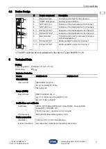
Page 25: ...el 1 7 DIP switch LF2 Activation of line fault detection for channel 2 9 Blue terminals Connection terminals for the hazardous area intrinsically safe Ex i 12 DIP switch LI1 Additional HART resistor f...

Page 26: ...F Max connectable inductance Lo IIC 1 9 mH IIB IIIC 11 mH Internal capacitance Ci negligible Internal inductance Li negligible Safety related maximum voltage Um 253 V Technical Data Version 9165 6 11...

Page 27: ...ior of input 100 k Input current for line break detection 3 6 mA Settings Switch LF activated deactivated Error detection LED red LF each channel Signalization of faulty line and power supply failure...

Page 28: ...ICE Inadmissibly high ambient temperature in the switch cabinet Possible device failure Observe the notes in the document Cabinet installation guide download from the website r stahl com Make sure tha...

Page 29: ...the device Non compliance results in severe or fatal injuries Carry out installation strictly according to the instructions and national safety and accident prevention regulations to maintain the exp...

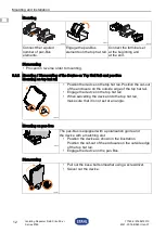
Page 30: ...lements on the top hat rail Connect the terminal set at the beginning and at the end 06886E00 Position the device on the top hat rail Position the cut out of the enclosure on the outside edge of the t...

Page 31: ...ons such as in particular on ships requires additional measures to be taken for correct installation depending on the place of use Further information and instructions on this can be obtained from you...

Page 32: ...ee HART communication Output of the connected automation system current source has low AC impedance Deactivate DIP switch LI depending on the channel switch position OFF Input resistance Ri of the iso...

Page 33: ...h LF1 or LF2 10 3 Troubleshooting Refer to the following troubleshooting plan for troubleshooting Line fault at the output Threshold value for line fault detection Behaviour of the input during line f...

Page 34: ...determine the type and extent of inspections Adapt inspection intervals to the operating conditions During maintenance of the device check at least whether the clamping screws holding the electric li...

Page 35: ...STAHL Schaltger te GmbH refer to chapter 1 1 for the address 12 Cleaning To avoid electrostatic charging the devices located in potentially explosive areas may only be cleaned using a damp cloth When...

Page 36: ......

Page 37: ...Id No 91 656 12 31 0 2 Intrinsically safe apparatus may be switches thermocouples LEDs RTDs or an FM Approved System or Entity device connected in accordance with the manufacturer s installation instr...

Reviews: