background image

279954 / 944260310110

2022-05-04·BA00·III·de·00

Montage und Installation

17

DE
EN

FR

IT

ES

RU

NL

DK

SE

FI

PT

GR

PL

CZ
SK

HU

SL

RO

BG

LV

LT

EE

CH

KR

CN

CPU Modul für Zone 1

Reihe 9442/32

Primäre Ethernet

-

Leitung mit Rasthaken am Standard-RJ45-Steckverbinder an die 

RJ45-Buchse X2P1 anschließen, bis dieser hörbar einrastet.

Sekundäre Ethernet

-

Leitung mit Rasthaken am Standard-RJ45-Steckverbinder an die 

RJ45-Buchse X2P2 anschließen, bis dieser hörbar einrastet.

Anschlussleitungen gegen Zugbelastung und Scheuern sichern.

Schirm der Ethernet

-

Leitung an mindestens einer Stelle mit dem Potentialausgleich 

verbinden.

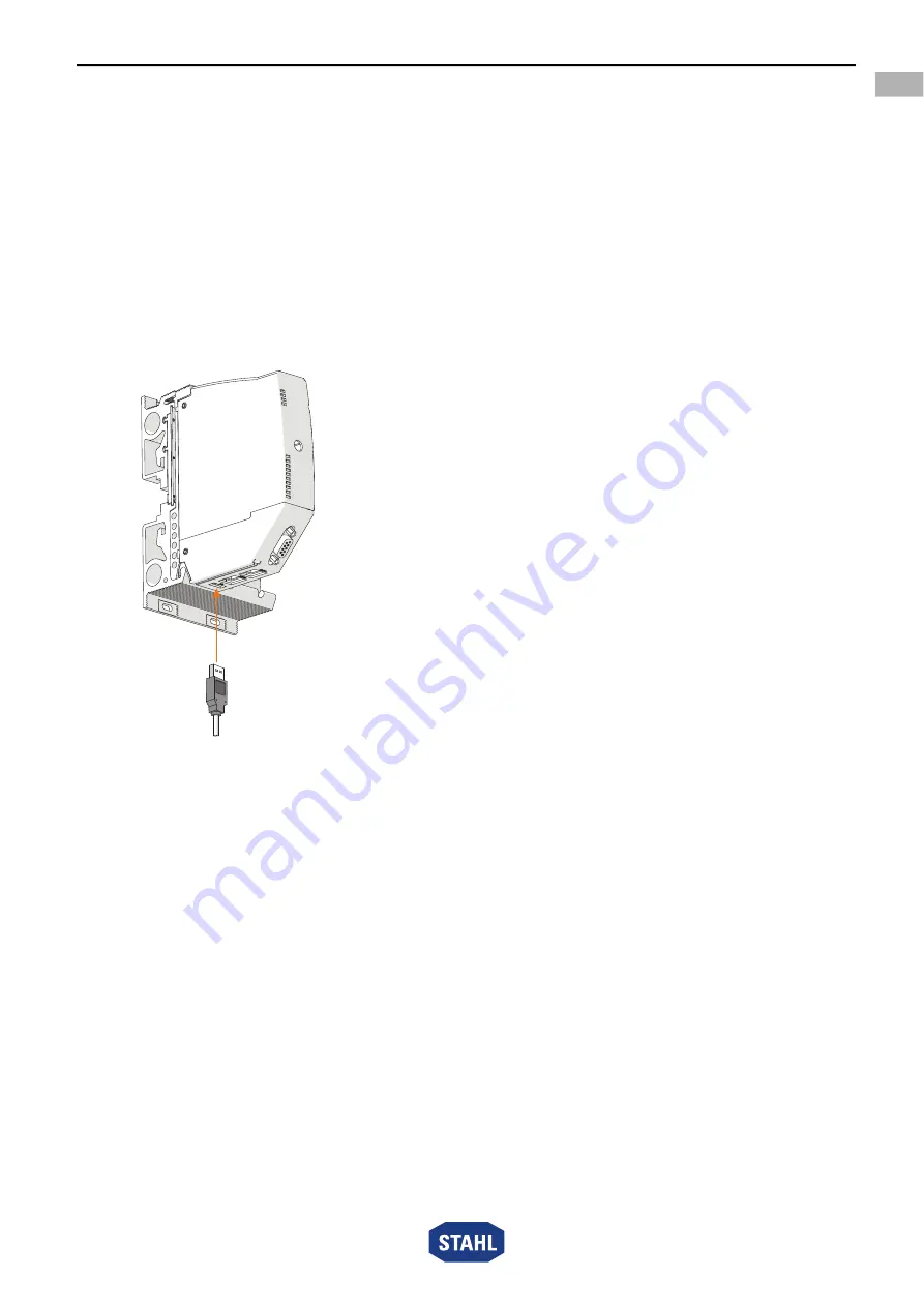
6.3.3 Eigensichere USB-Leitung anschließen

Bei Einsatz in explosionsgefährdeten Bereichen müssen zwischen dem eigensicheren 

USB-Anschluss (X3) und dem PC immer ein geeigneter Ex i USB RS485 Converter 

(z.B. Reihe 9787/12) und Feldbus-Trennübertrager (z.B. Reihe 9185) eingesetzt werden.

23117E00

USB-Leitung mit USB-Stecker an die USB-Buchse X3 anschließen.

Anschlussleitung gegen Zugbelastung und Scheuern sichern.

Summary of Contents for 279953

Page 1: ...CPU Modul für Zone 1 Reihe 9442 32 Betriebsanleitung Additional languages r stahl com DE EN FR IT ES RU NL DK SE FI PT GR PL CZ SK HU SL RO BG LV LT EE CH KR CN Für künftige Verwendung aufbewahren ...

Page 2: ... 5 1 Anschlussbelegung Sub D Buchse X1 9 5 2 Anschlussbelegung RJ45 Buchsen X2 10 5 3 Buchse USB 2 0 Typ A X3 10 5 4 Redundanz 11 6 Montage und Installation 13 6 1 Montage Demontage 13 6 2 Austausch und Upgrade des Moduls 14 6 3 Installation 15 7 Parametrierung und Inbetriebnahme 18 7 1 Software Update 18 8 Betrieb 18 8 1 Betrieb 18 8 2 Anzeigen 18 8 3 Fehlerbeseitigung 19 9 Instandhaltung Wartung...

Page 3: ...Diese ist rechtsverbindlich in allen juristischen Angelegenheiten 1 3 Weitere Dokumente Kopplungsbeschreibungen IS1 Download unter r stahl com Installation RS485 Download unter r stahl com Datenblatt 9442 32 Datenblatt 9445 32 Datenblatt 9496 32 Betriebsanleitung Power Module 9445 32 Betriebsanleitung Sockel 9496 32 Betriebsanleitung CPM 9440 22 Sockel 9490 Betriebsanleitung CPU 9441 12 Power Modu...

Page 4: ...efahrensituation die bei Nichtbeachtung der Sicherheitsmaßnahmen zu leichten Verletzungen führen kann HINWEIS Gefahrensituation die bei Nichtbeachtung der Sicherheitsmaßnahmen zu Sachschäden führen kann Symbol Bedeutung 05594E00 CE Kennzeichnung gemäß aktuell gültiger Richtlinie 02198E00 Gerät gemäß Kennzeichnung für explosionsgefährdete Bereiche zertifiziert 11048E00 Sicherheitshinweise welche un...

Page 5: ...me und Plant Asset Management Tools erfolgt über Standards wie GSD EDS sowie Webserver und FDT DTM Das Gerät ist für den Einsatz im explosionsgefährdeten Bereich der Zone 1 Zone 2 und im sicheren Bereich zugelassen Die eigensicheren Stromkreise sind für die Zonen 1 und 2 sowie 21 und 22 geeignet Zur bestimmungsgemäßen Verwendung gehören diese Betriebsanleitung und die mitgeltenden Dokumente z B da...

Page 6: ...chützt Bei der Auswahl der Transportverpackung Umgebungsbedingungen siehe Kapitel Technische Daten berücksichtigen Gerät nicht belasten Verpackung und Gerät auf Beschädigung prüfen Beschädigungen umgehend an R STAHL melden Beschädigtes Gerät nicht in Betrieb nehmen Gerät in Originalverpackung trocken keine Betauung in stabiler Lage und sicher vor Erschütterungen lagern Gerät und weitere Systemkomp...

Page 7: ...andhaltung nur durch qualifizierte und autorisierte Personen siehe Kapitel 3 2 durchführen lassen Gerät nicht ändern oder umbauen Gerät bei Einsatz in explosionsfähiger Atmosphäre in ein schützendes Gehäuse oder einen Schaltschrank einbauen das einer anerkannten Zündschutzart nach IEC EN 60079 0 entspricht und eine Schutzart von mindestens IP54 gemäß IEC EN 60529 aufweist Gerät bei Einsatz im sich...

Page 8: ...orgfältig und unter Beachtung der Sicherheitshinweise siehe Kapitel Sicherheit transportieren und lagern 5 Produktauswahl und Projektierung Bei Neuprojektierung oder Umbau eines Remote I O Systems IS1 sind folgende Bedingungen zu berücksichtigen und einzuhalten Arbeitsweise Die CPU kommuniziert mit den installierten I O Modulen über den Sockel und die Adress und Datenleitungen der BusRail Die Konf...

Page 9: ...ierzu Details in den jeweiligen Kopplungsbeschreibungen IS1 Maximale Systemlänge BusRail BusRail Verlängerung von 3 m einhalten Alle Anschlussleitungen gegen Zugbelastung und Scheuern sichern Bei eigensicheren und nicht eigensicheren Stromkreisen einen Abstand von min 50 mm einplanen Projektierungsvorgaben in Abhängigkeit der Umgebungstemperatur Befestigung je nach maximaler Umgebungstemperatur au...

Page 10: ...X3 Schnittstelle für den Servicebus bei Feldbus Kommunikation Pin Paar Pin Nr Funktion Beschreibung 19623E00 1 4 nicht angeschlossen 5 nicht angeschlossen 2 1 RD Receive Data 2 RD Receive Data 3 3 TD Transmit Data 6 TD Transmit Data 4 7 nicht angeschlossen 8 nicht angeschlossen Intern sind die RJ45 Buchsen als 2 Port Switch ausgeführt Bei PROFIBUS DP ist nur der Ethernet Port X2P1 aktiv und es ist...

Page 11: ...ligen Redundanzkonzepte Auswahl des geeigneten Sockels 9496 32 und die maximale Bestückung der CPU Module 9442 32 und Power Module 9445 32 beachten Sockel 9496 32 CPU Modul 9442 32 Power Modul 9445 32 Keine Redundanz mit 3 Steckplätzen 1 x CPU Modul gilt für alle Protokolle 1 x Power Modul CPU Redundanz mit 3 Steckplätzen 2 x CPU Modul PROFIBUS DP Modbus TCP 1 x Power Modul Power Redundanz mit 3 S...

Page 12: ...on ausgeliefert Sie kann daher von der Version eines älteren bereits verwendeten Moduls abweichen Bei Kombination eines neuen mit einem älteren CPU Modul die Firmware Versionen abgleichen Mindestens ein Modul bis einschließlich Firmware Version V1 0 21 Beide Module ab Firmware Version V1 0 22 Alle Firmware Versionen sind zueinander kompatibel HINWEIS Fehlfunktion durch den Einsatz nicht kompatible...

Page 13: ...ren siehe Betriebsanleitung 9496 32 Am CPU Modul prüfen ob die Feder 1 vorhanden ist Nur so ist eine korrekte Wärmeableitung über den Sockel gewährleistet CPU Modul nur auf den Steckplatz Slot 0 oder 1 stecken CPU Modul unten in den Sockel einhängen 1 und einschwenken 2 CPU Modul mit Sicherungsschraube 3 mit einem Schraubendreher Torx T20 befestigen Anzugsdrehmoment 1 5 1 9 Nm GEFAHR Explosionsgef...

Page 14: ...FIBUS CPM Reihe 9440 22 auf IS1 CPU 9442 32 Stromversorgung der IS1 Remote I O Station abschalten Anschlussleitungen für Kommunikation trennen siehe Betriebsanleitung 9440 22 CPM 9440 22 und Sockel 9490 demontieren siehe Betriebsanleitung 9440 22 und 9490 Sockel 9496 32 montieren siehe Betriebsanleitung 9496 32 CPU Modul 9442 32 montieren siehe Kapitel 6 1 2 Power Modul 9445 32 montieren siehe Bet...

Page 15: ...alten 6 3 Installation Anders als beim IS1 Ethernet Sockel 9492 12 wird der Sockel 9496 32 der IS1 CPU auf den Steckplatz Slot 0 der BusRail aufgesteckt Dadurch verschieben sich alle I O Module um einen Steckplatz Slot n 1 Anschließend muss das System neu konfiguriert werden Wenn Platz vorhanden ist kann auch eine BusRail 9494 S1 B2 zusätzlich an den Anfang gesteckt werden Siehe auch Dokument IS1 ...

Page 16: ... werden 23119E00 Feldbus Leitung mit Sub D Stecker an Sub D Buchse X1 anschließen Sub D Stecker mit Schrauben gegen Lockern sichern Anzugsdrehmoment 0 5 0 6 Nm Anschlussleitung gegen Zugbelastung und Scheuern sichern Schirm des Feldbusses an mindestens einer Stelle mit dem Potentialausgleich verbinden siehe Dokument Installation RS485 6 3 2 Eigensichere Ethernet Leitung anschließen Bei Einsatz in ...

Page 17: ...Buchse X2P2 anschließen bis dieser hörbar einrastet Anschlussleitungen gegen Zugbelastung und Scheuern sichern Schirm der Ethernet Leitung an mindestens einer Stelle mit dem Potentialausgleich verbinden 6 3 3 Eigensichere USB Leitung anschließen Bei Einsatz in explosionsgefährdeten Bereichen müssen zwischen dem eigensicheren USB Anschluss X3 und dem PC immer ein geeigneter Ex i USB RS485 Converter...

Page 18: ...zustand des Geräts an siehe auch Kapitel Bestimmungsgemäße Verwendung und Geräteaufbau Parametrierung siehe entsprechende Kopplungsbeschreibung IP Adresseinstellung für Service Bus manuell oder DHCP Zuweisung vom Anwender über via Webserver oder IS1 Detect Software wählbar Default 192 168 1 101 Hinweis Wird die Einstellung DHCP gewählt und es ist kein DHCP Server erreichbar wird automatisch die al...

Page 19: ...orhanden Falsche s Modul e gesteckt Modul e tauschen Modul e stecken Richtige s Modul e stecken LED ERR rot erloschen Kein Fehler LED M S blau leuchtet Wartungsbedarf Ungünstige Betriebsbedingungen Modul tauschen empfohlen LED M S blau blinkt und LED PWR grün leuchtet Außerhalb Spezifikation Die Temperatur um die CPU ist zu hoch oder zu niedrig Umgebungstemperatur ändern oder für bessere Belüftung...

Page 20: ...n leuchtet Datenaustausch mit AS und CPU Aktivität Datenaustausch und CPU aktiv LED AS EXCH grün blinkt Datenaustausch mit AS und CPU Aktivität Datenaustausch und CPU inaktiv nur bei redundanten CPUs LED AS EXCH grün erloschen Datenaustausch mit AS und CPU Aktivität Kein Datenaustausch mit AS Zyklischen Datenverkehr mit dem Master in Betrieb setzen Master und Busverbindung zu CPU prüfen LED CFG ER...

Page 21: ...g Einsatzzweck insbesondere Eingangs Ausgangsbeschaltung LED Zustand Status Fehlerursache Fehlerbehebung LED RS485 grün LED ACT grün und LED USB grün blinken Datenverkehr Kein Fehler LED RS485 grün LED ACT grün und LED USB grün leuchten sehr hoher Datenverkehr Kein Fehler LED LNK gelb leuchtet Physikalische Verbindung vorhanden Kein Fehler LED LNK gelb erloschen Physikalische Verbindung getrennt o...

Page 22: ...apitel Sicherheit warten 9 3 Reparatur Reparaturen am Gerät nur durch R STAHL durchführen lassen 10 Rücksendung Rücksendung bzw Verpackung der Geräte nur in Absprache mit R STAHL durchführen Dazu mit der zuständigen Vertretung von R STAHL Kontakt aufnehmen Für die Rücksendung im Reparatur bzw Servicefall steht der Kundenservice von R STAHL zur Verfügung Kundenservice persönlich kontaktieren oder I...

Page 23: ...den Gerät nur mit feuchtem Tuch und ohne kratzende scheuernde oder aggressive Reinigungsmittel oder Lösungen schonend reinigen 12 Entsorgung Nationale und lokal gültige Vorschriften und gesetzliche Bestimmungen zur Entsorgung beachten Materialien getrennt dem Recycling zuführen Umweltgerechte Entsorgung aller Bauteile gemäß den gesetzlichen Bestimmungen sicherstellen 13 Zubehör und Ersatzteile HIN...

Page 24: ...x ATEX Schiffszertifikate In Vorbereitung Weitere Parameter Installation in Zone 1 Zone 2 und im sicheren Bereich Weitere Angaben siehe Betriebsanleitung und Bescheinigungen Sicherheitstechnische Daten Steckplatz Anschluss Max Eingangs spannung Ui zum Anschluss an Buchse 9496 3 26 2 V Schnittstelle X1 RS485 RS485 IS gemäß Zündschutzart Ex ia Ga IIC und Ex ia Da IIIC Hinweis Galvanisch getrennte In...

Page 25: ...s gemäß Zündschutzart Ex ib Gb IIC oder IIB und Ex ib Db IIIC Hinweis Galvanisch getrennte Installation der Kommunikationsleitungen und des Schirms Nur zum Anschluss von passiven Bauteilen ohne Einspeisung in den eigensicheren Stromkreis Max Spannung Um 30 V DC Max Ausgangs spannung Uo 5 55 V DC Max Strom Imax 250 mA Max Ausgangs strom Io 687 mA DC rechteckige Quelle Max Ausgangs leistung Po 2 W M...

Page 26: ...6 kbit s 12 Mbit s Max Leitungslänge Kupferleitung 1200 m bei 9 6 93 75 kbit s 1000 m bei 187 5 kbit s 400 m bei 500 kbit s 200 m bei 1 5 Mbit s 100 m bei 12 Mbit s Lichtwellenleiter 2000 m bei 1 5 Mbit s mit LWL Feldbus Trennübertrager 9186 siehe Zubehör Schnittstelle X2 10 100 BASE TX IS Anschluss 2 x RJ45 Stecker 100 BASE TX IS Unmanaged Switch Funktion Protokolle Modbus TCP PROFINET EtherNet I...

Page 27: ...r Ethernet Port 1 LED ACT P1 grün Portverbindung Ethernet Port 2 LED LNK P2 gelb Datenverkehr Ethernet Port 2 LED ACT P2 grün Datenverkehr USB LED USB grün Diagnose und Parametrierung Funktionen IP Adresse einstellen über Webserver oder IS1 Detect Software bei Ethernet Webserver Konfigurationsdaten und Parameter in IS1 Feldstationen laden oder rücklesen Eingänge lesen Ausgänge lesen und schreiben ...

Page 28: ... von min 3 mm oder Material mit besserer Wärmeleitfähigkeit z B Aluminium mit vier oder sechs zusätzlichen Sicherheitsschrauben Lagertemperatur 40 80 C Maximale relative Luftfeuchte 95 ohne Betauung Maximale Betriebshöhe 2000 m Schock halbsinusförmig IEC EN 60068 2 27 15 g 3 Schocks pro Achse und Richtung Vibration sinusförmig IEC EN 60068 2 6 1 g im Frequenzbereich 10 500 Hz 2 g im Frequenzbereic...

Page 29: ...bzw Fehleranzeige der CPU 3 LEDs Status bzw Fehleranzeige der Kommunikation zum Automatisierungs system 4 LEDs Statusanzeige der Schnittstellen 5 Sub D Buchse RS485 Buchse X1 Prozessbus 6 Beschriftung Angaben zum Modul Seriennummer Hardware Revisions nummer Software Revisionsnummer Herstelldatum z B 12345678914 004 Rev A 01 01 0514 7 RJ45 Buchse Industrial Ethernet Buchsen X2 Px P1 Prozessbus Serv...

Page 30: ... für Zone 1 Reihe 9442 32 15 2 Maßangaben Befestigungsmaße Maßzeichnungen alle Maße in mm Zoll Änderungen vorbehalten 22970E00 22971E00 CPU Modul 9442 32 CPU Modul 9442 32 mit Sockel 9496 32 3 Steckplätze 23022E00 CPU Modul 9442 32 mit Sockel 9496 32 4 Steckplätze 123 4 84 158 6 22 32 1 26 167 6 57 96 3 78 152 5 98 152 5 98 152 5 98 167 6 57 ...

Page 31: ...ionen zu der mit den IS1 9442 CPUs augelieferten Open Source Software und oder über die R STAHL Website heruntergeladene Open Source Software verweisen wir auf die in der IS1 9442 CPU Firmware in den IS1 9442 CPU Firmware Update ZIP Files sowie auf der R STAHL Webseite enthaltenen License Info Open Source Software Die IS1 9442 CPU Firmware Update ZIP Files sowie die License Info Open Source Softwa...

Page 32: ......

Page 33: ...CPU module for Zone 1 Series 9442 32 Operating instructions Additional languages r stahl com DE EN FR IT ES RU NL DK SE FI PT GR PL CZ SK HU SL RO BG LV LT EE CH KR CN Save for future use ...

Page 34: ...l Assignment for Sub D Slot X1 9 5 2 Terminal Assignment X2 RJ45 Slots 10 5 3 Type A X3 USB 2 0 Socket 10 5 4 Redundancy 11 6 Mounting and Installation 13 6 1 Mounting Dismounting 13 6 2 Replacing and Upgrading the Module 14 6 3 Installation 15 7 Parameterisation and Commissioning 18 7 1 Software Update 18 8 Operation 18 8 1 Operation 18 8 2 Displays 18 8 3 Troubleshooting 19 9 Maintenance Overhau...

Page 35: ...n edition They are legally binding in all legal affairs 1 3 Further Documents IS1 coupling descriptions download at r stahl com Installation of RS485 download at r stahl com Data sheet 9442 32 Data sheet 9445 32 Data sheet 9496 32 9445 32 power modules operating instructions 9496 32 socket operating instructions 9440 22 CPU 9490 socket operating instructions 9441 12 CPU 9444 power module 9492 sock...

Page 36: ...lied with CAUTION Dangerous situation which can result in minor injuries if the safety measures are not complied with NOTICE Dangerous situation which can result in material damage if the safety measures are not complied with Symbol Meaning 05594E00 CE marking according to the current applicable directive 02198E00 Device certified for hazardous areas according to the marking 11048E00 Safety notes ...

Page 37: ...il Integration in control systems and plant asset management tools is implemented using standards such as GSD EDS web servers and FDT DTM The device is approved for use in hazardous areas of Zones 1 and 2 and in safe areas The intrinsically safe electrical circuits are suitable for Zone 1 and Zone 2 and Zone 21 and 22 Intended use includes complying with these operating instructions and the other ...

Page 38: ...port packaging see the Technical data chapter Do not place any loads on the device Check the packaging and the device for damage Report any damage to R STAHL immediately Do not commission a damaged device Store the device in its original packaging in a dry place with no condensation and make sure that it is stable and protected against the effects of vibrations and knocks Do not damage the device ...

Page 39: ...ssioning and maintenance work performed by qualified and authorised persons see chapter 3 2 Do not change or modify the device For use in an explosive atmosphere install the device in a protective enclosure or cabinet that corresponds to a recognised type of protection in accordance with IEC EN 60079 0 and a degree of protection of at least IP54 in accordance with IEC EN 60529 For use in a safe ar...

Page 40: ...n accordance with the safety information see Safety chapter 5 Product Selection and Project Engineering During new project engineering or modification of an IS1 Remote I O system the following conditions are to be taken into account and adhered to Mode of operation The CPU communicates with the installed I O modules over the socket and the address and data lines of the BusRail The configuration pa...

Page 41: ...ils on this see the corresponding IS1 coupling descriptions Adhere to the maximum system length BusRail BusRail extension of 3 m Secure all connection lines against tensile load and scuffing Plan a distance of at least 50 mm for intrinsically safe and non intrinsically safe electrical circuits Project engineering specifications depending on the ambient temperature Adjust mounting processes based o...

Page 42: ...Type A X3 USB 2 0 Socket Interface for the ServiceBus for fieldbus communication Pin pair Pin no Function Description 19623E00 1 4 Not connected 5 Not connected 2 1 RD Receive Data 2 RD Receive Data 3 3 TD Transmit Data 6 TD Transmit Data 4 7 Not connected 8 Not connected Internally the RJ45 sockets as designed as 2 port switches For PROFIBUS DP only the X2P1 Ethernet port is active and there is n...

Page 43: ...or the respective redundancy concepts Comply with the specifications for selecting the suitable 9496 32 socket and maximum equipping of the 9442 32 CPU module and 9445 32 power module 9496 32 socket 9442 32 CPU module 9445 32 power module No redundancy With 3 slots 1 x CPU module applies for all protocols 1 x power module CPU redundancy With 3 slots 2 x CPU module PROFIBUS DP Modbus TCP 1 x power ...

Page 44: ... the latest firmware version It may differ from the version already used by an older module When combining a new CPU module with an older one match the firmware versions At least one module up to and including firmware version V1 0 21 Both modules from firmware version V1 0 22 All firmware versions are compatible with each other NOTICE Malfunction due to use of incompatible firmware versions Non c...

Page 45: ...socket see 9496 32 operating instructions Check whether the spring 1 is present on the CPU module This is the only way to guarantee that heat is dissipated correctly across the socket Plug the CPU module only into the slot slot 0 or 1 Hang 1 the CPU module on the bottom of the socket and swivel it inward 2 Secure the CPU module using a safety screw 3 and a screwdriver Torx T20 Tightening torque 1 ...

Page 46: ... the 9440 22 IS1 PROFIBUS CPM Series to 9442 32 IS1 CPU Switch off the power supply to the IS1 Remote I O station Disconnect the connection lines for communication see 9440 22 operating instructions Dismount the 9440 22 CPM and 9490 socket see 9440 22 and 9490 operating instructions Mount the 9496 32 socket see 9496 32 operating instructions Mount the 9442 32 CPU module see chapter 6 1 2 Mount the...

Page 47: ...y power see 9445 32 operating instructions Switch the power supply back on 6 3 Installation Unlike the 9492 12 IS1 Ethernet socket the 9496 32 socket of the IS1 CPU is connected to the slot slot 0 on the BusRail This moves all I O modules by one slot slot n 1 Then the system has to be reconfigured If there is space available a 9494 S1 B2 BusRail can also be connected at the beginning See also the ...

Page 48: ...3119E00 Connect the fieldbus conductor with Sub D plug to the X1 Sub D slot Secure the Sub D connector against loosening using screws Tightening torque 0 5 to 0 6 Nm Secure the connection line against tensile load and scuffing Connect the shielding of the fieldbus to the equipotential bonding at at least one point see Installation for RS485 documentation 6 3 2 Connect Intrinsically Safe Ethernet L...

Page 49: ...g connector to the X2P2 RJ45 socket until it audibly engages Secure connection lines against tensile loads and scuffing Connect at least one point of the shielding of the Ethernet line with the equipotential bonding 6 3 3 Connecting an Intrinsically Safe USB Cable For use in hazardous areas a suitable Ex i USB RS485 converter e g series 9787 12 and fieldbus isolating repeater e g series 9185 must ...

Page 50: ...ting state of the device see also the Intended use and Device design chapters For information on parameterisation see the corresponding coupling description IP address setting for ServiceBus manual or DHCP assignment can be selected by the user via a web server or IS1 detect software Default 192 168 1 101 Note If the DHCP setting is selected and no DHCP server can be reached the alternative IP add...

Page 51: ...e s not available Incorrect module s connected Replace the module s Connect the module s Connect the correct module s PWR LED red is off No error M S LED blue lights up Maintenance required Unfavourable operating conditions Replace module recommended M S LED blue blinking and PWR LED green lights up Outside the specification The temperature around the CPU is too high or too low Change the ambient ...

Page 52: ... green lights up Data exchange with AS and CPU activity Data exchange and CPU active AS EXCH LED green blinking Data exchange with AS and CPU activity Data exchange and CPU inactive only for redundant CPUs AS EXCH LED green is off Data exchange with AS and CPU activity No data exchange with AS Activate the cyclical data transfer with the master Check the master and bus connection to the CPU CFG ER...

Page 53: ...ion Intended purpose especially input output circuit LED status Status Cause of error Troubleshooting The RS485 LED green ACT LED green and USB LED green are blinking Data traffic No error The RS485 LED green ACT LED green and USB LED green light up Very high data traffic No error LNK LED yellow lights up Physical connection available No error The LNK LED yellow is off The physical connection is d...

Page 54: ...cable national regulations and the safety notes in these operating instructions Safety chapter 9 3 Repair Repair work on the device must be performed only by R STAHL 10 Returning the Device Only return or package the devices after consulting R STAHL Contact the responsible representative from R STAHL R STAHL s customer service is available to handle returns if repair or service is required Contact...

Page 55: ...e Gently clean the device with a damp cloth only do not use scratching abrasive or aggressive cleaning agents or solutions 12 Disposal Observe national local and statutory regulations regarding disposal Separate materials for recycling Ensure environmentally friendly disposal of all components according to statutory regulations 13 Accessories and Spare Parts NOTICE Malfunction or damage to the dev...

Page 56: ...ifications IECEx ATEX Ship certificates In progress Further parameters Installation in Zone 1 Zone 2 and safe area Further information See operating instructions and certificates Safety data Slot connection Max Input voltage Ui For connection to the 9496 3 socket 26 2 V X1 RS485 RS485 IS interface According to type of protection Ex ia Ga IIC and Ex ia Da IIIC Note Galvanically separated installati...

Page 57: ...ccording to type of protection Ex ib Gb IIC or IIB and Ex ib Db IIIC Note Galvanically separated installation of communication lines and shield Only for connection of passive components without supply in the intrinsically safe electrical circuit Max Voltage Um 30 V DC Max Output voltage Uo 5 55 V DC Max Current Imax 250 mA Max Output current Io 687 mA DC rectangular source Max Output power Po 2 W ...

Page 58: ...ate Profibus DP 9 6 kbps to 12 Mbps Max conductor length Copper conductor 1200 m at 9 6 to 93 75 kbps 1000 m at 187 5 kbps 400 m at 500 kbps 200 m at 1 5 Mbps 100 m at 12 Mbps Fibre optics 2000 m at 1 5 Mbps with 9186 FO fieldbus isolating repeater see accessories X2 10 100 BASE TX IS interface Connection 2 x RJ45 plug 100 Base TX IS unmanaged switch function Protocols Modbus TCP PROFINET Ethernet...

Page 59: ... green Ethernet port 2 connection LNK P2 LED yellow Ethernet port 2 data traffic ACT P2 LED green USB data traffic USB LED green Diagnostics and parameterisation Functions Use the web server or IS1 detect software to set the IP address for Ethernet Web server Load or read back configuration data and parameters in IS1 field stations Read inputs Read and write outputs Transmit diagnostics data e g c...

Page 60: ... at least 3 mm or material with better heat conductivity e g aluminium with four or six additional safety screws Storage temperature 40 to 80 C Maximum relative humidity 95 without condensation Maximum operating height 2000 m Semi sinusoidal shock IEC EN 60068 2 27 15 g 3 shocks per axis and direction Vibration sinusoidal IEC EN 60068 2 6 1 g in the frequency range of 10 to 500 Hz 2 g in the frequ...

Page 61: ...or indication of the CPU 3 LEDs Status or error indication of communication to the automation system 4 LEDs Status indication of the interfaces 5 Sub D socket X1 RS485 Sub D socket process bus 6 Labelling Module data serial number hardware revision number software revision number date of manufacture e g 12345678914 004 Rev A 01 01 0514 7 RJ45 socket X2 Px industrial Ethernet sockets P1 process bus...

Page 62: ... for Zone 1 Series 9442 32 15 2 Dimensions Fastening Dimensions Dimensional drawings all dimensions in mm inch Subject to change 22970E00 22971E00 9442 32 CPU module 9442 32 CPU module with 9496 32 socket 3 slots 23022E00 9442 32 CPU module with 9496 32 socket 4 slots 123 4 84 158 6 22 32 1 26 167 6 57 96 3 78 152 5 98 152 5 98 152 5 98 167 6 57 ...

Page 63: ...ce parts of the software For further information regarding the open source software delivered with the IS1 9442 CPUs and or open source software downloaded via the R STAHL website we refer to the License Info Open Source Software contained in the IS1 9442 CPU firmware in the IS1 9442 CPU firmware update ZIP files and on the R STAHL website The IS1 9442 CPU firmware update ZIP files and the License...

Page 64: ...2 G Ex ib ia Ga ib Gb IIC T4 Gb r r II 1 2 D Ex ia Da Ex ib Db IIIC EU Baumusterprüfbescheinigung EU Type Examination Certificate Attestation d examen UE de type PTB 21 ATEX 2004 X Physikalisch Technische Bundesanstalt Bundesallee 100 38116 Braunschweig Germany NB0102 Produktnormen nach Niederspannungsrichtlinie Product Standards according to Low Voltage Directive Normes des produit pour la Direct...

Reviews: