279954 / 944260310110
2022-05-04·BA00·III·en·00
Appendix A
25
DE
EN
FR
IT
ES
RU
NL
DK
SE
FI
PT
GR
PL
CZ
SK
HU
SL
RO
BG
LV
LT
EE
CH
KR
CN
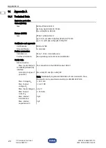
CPU module for Zone 1
Series 9442/32
Explosion protection
X2 10/100-BASE-TX-IS
interface
According to type of
protection
[Ex ia Ga] IIC and [Ex ia Da] IIIC
Note: Galvanically separated installation of communication lines;
the shield can be grounded according to IEC/EN 60079-14.
It is a point-to-point connection.
The persistent current on the signal lines is protected internally at
max. 213 mA. The communication partner (e.g. media converter, switch),
must limit this current to max. 425 mA.
Max. Output
voltage U
o
≤ 5.0 V
Max. Input voltage U
i
5.0 V
Max. Current I
o
≤ 425 mA
Max. internal
inductance L
i
200 nH
Max. internal
capacitance C
i
0 µF
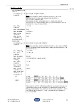
X3 USB IS interface
(ServiceBus)
According to type of
protection
[Ex ib Gb] IIC or IIB and [Ex ib Db] IIIC
Note: Galvanically separated installation of communication lines and shield.
Only for connection of passive components without supply in the intrinsically
safe electrical circuit.
Max. Voltage U
m
≤ 30 V DC
Max. Output
voltage U
o
≤ 5.55 V DC
Max. Current I
max
250 mA
Max. Output
current I
o
≤ 687 mA DC (rectangular source)
Max. Output
power P
o
≤ 2 W
Max. internal
inductance L
i
0 µH
Max. internal
capacitance C
i
1.6 µF
Max. connectable
inductance L
o
/
Capacitance C
o
IIC
L
o
[µH]
150 100 50
20
10
5
2
1
C
o
[µF]
0.5
1.5
3.4
6.6
10.4 16.4 38.4 52.4
IIB/IIIC
L
o
[µH]
610 500 200 100 50
20
10
5
2
C
o
[µF]
6.3
8.3
17.4 26.4 38.4 66.4 118.4 288.4 998.4
The values of L
o
and C
o
in the table are the maximum values for combined
inductance and capacitance (including line inductance and capacitance).
The grey-marked values for L
o
and C
o
are the maximum values for L
o
and C
o
.
The internal capacitance of C
i
= 1.6 µF is entered into the calculation of
values in the table.
Summary of Contents for 279953
Page 32: ......


