background image

202161 / 815060300020

2016-12-13·BA00·III·en·05

Commissioning

19

EN
EN
EN
EN
EN
EN
EN
EN
EN
EN
EN
EN
EN
EN
EN
EN
EN
EN
EN
EN
EN
EN
EN
EN
EN

Terminal Box

Series 8150/1, Series 8150/2

Clearance and creepage distances of intrinsically safe components

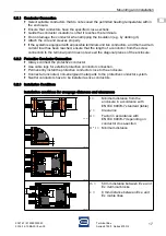
Make sure that the creepage distances and clearances between the uncoated, conductive 

parts of connection terminals of separated, intrinsically safe circuits to earthed or  

potential-free, conductive parts is equal or greater than the values of EN IEC 60079-11, 

Table 5.

For separated, intrinsically safe electric circuits, set up a safe distance between  

the uncoated, conductive parts of external connections, which meets the following  

requirements:

• minimum 6 mm between the separated, intrinsically safe circuits

• minimum 3 mm to earthed parts if possible connection to earth has not been considered 

in the safety analysis.

7

Commissioning

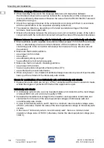
Before commissioning, carry out the following checks:

Check the enclosure for damage.

Check that mounting and installation have been performed correctly. When doing so, 

check whether all covers and partitions for live parts have been installed and fastened.

Make sure that all openings/drilled holes in the enclosure are sealed with permissible  

components. Dust and transport protection (adhesive tape or plastic caps) fitted at  

the factory must be replaced with certified components.

Make sure that seals and sealing systems are clean and undamaged.

If necessary, remove foreign bodies.

If necessary, clean the connection chamber.

Check whether all prescribed tightening torques have been observed.

8

Maintenance, overhaul, repair

Observe the relevant national regulations in the country of use, e.g. EN IEC 60079-14,  

EN IEC 60079-17, EN IEC 60079-19.

8.1

Maintenance

Check the following points in addition to the national regulations:

• whether the clamping screws holding the cables are securely seated, 

• whether the device enclosure and / or protective enclosure have cracks or other visible 

signs of damage,

• compliance with the permitted temperatures,

• whether the nut is securely seated.

8.2

Maintenance

Perform maintenance on the device according to the applicable national regulations  

and the safety notes in these operating instructions (chapter 3).

8.3

Repair

Perform repairs to the device only using original spare parts and after consulting with  

R. STAHL.

Summary of Contents for 8150/1 Series

Page 1: ...EN EN EN EN EN EN EN EN EN EN EN EN EN EN EN EN EN EN EN EN EN EN EN EN EN Operating Instructions Additional Languages Www stahl ex com En Terminal Box Series 8150 1 Series 8150 2 Save For Future Use ...

Page 2: ... storage 7 5 Product selection project engineering and modification 7 5 1 Additional through holes in flange plates 8 5 2 Additional through holes in the enclosure 9 5 3 External attached components cable entries stopping plugs breathers 11 5 4 Internal built in components conductors terminals fuses 12 6 Mounting and installation 15 6 1 Mounting dismounting operating position 15 6 2 Installation 1...

Page 3: ...ng instructions throughout the service life of the device Make the operating instructions accessible to operating and maintenance personnel at all times Pass the operating instructions on to each subsequent owner or user of the device Update the operating instructions every time you receive an amendment to them from R STAHL ID No 202161 815060300020 Publication Code 2016 12 13 BA00 III en 05 The o...

Page 4: ...x is manufactured in various sizes and can be combined to create larger distribution units Intended use includes observing these operating instructions and the other applicable documents e g the data sheet All other use of the terminal box is not intended 3 2 Personnel qualification Qualified specialist personnel are required to perform the tasks described in these operating instructions This prim...

Page 5: ...form all work steps in hazardous areas with the utmost care at all times Possible moments of danger residual risks can be categorised according to the following causes Mechanical damage The device can be pressed or scratched during transport mounting or commissioning causing it to no longer be leak tight Such damage can for example render the device s explosion protection partially or fully ineffe...

Page 6: ...lling any additional holes Only drill holes for cable glands exactly according to the instructions in the Product selection project engineering and modification and Mounting chapters of these operating instructions Consult with R STAHL first if there are any discrepancies or uncertainties Mount the device only in the prescribed mounting position More detailed explanations of this can be found in t...

Page 7: ...rminals 4 Transport and storage Transport and store the device carefully and in accordance with the safety notes see chapter 3 5 Product selection project engineering and modification DANGER Explosion due to damaged seal in devices with enclosure hinges Non compliance results in fatal or severe injuries Devices with enclosure hinges must be transported only with a transport lock DANGER Explosion d...

Page 8: ...ernal built in components either by R STAHL or by the customer section 5 4 5 1 Additional through holes in flange plates 5 1 1 Creation of additional drilled holes and through holes by R STAHL Forward the following information to R STAHL Type Data sheet Quantity manufacturers and approvals of the components that are to be installed R STAHL will check whether the components drilled hole diameters q...

Page 9: ...he safety notes see chapter 3 Calculate the usable area see section 5 1 2 Create additional through holes by lasing or punching drilling hole cutting Ensure that the surfaces remain flat during punching and cutting Determine the core hole diameter for threads Do not use an NPT thread When determining the through holes observe the mounting distances Adjust the hole diameters to the dimensions of th...

Page 10: ...e total usable area The total usable area for installation is calculated as follows Length of the inner enclosure wall 2 x 10 mm x Height of the inner enclosure wall 2 x 10 mm 2 x 10 mm circumferential rim of the inner enclosure wall 2 Calculate the required area for cable entries Multiply the quantity of desired cable entries by the space requirement values of the appropriate type from the follow...

Page 11: ...ers to the dimensions of the built in parts or their seals The use of built in components with flat seal gasket is preferred Observe section 6 3 Cable entries stopping plugs breathers when subsequently equipping components 5 3 External attached components cable entries stopping plugs breathers Calculation example Starting conditions Dimensions of inner enclosure wall 297 mm Side D x 122 mm Side C ...

Page 12: ...which are permanently installed for electric lines which are not permanently installed Plastic or metal cable entries with strain relief Closing of unused entries Plastic or metal stopping plugs Drainage and pressure equalisation prevention of the vacuum effect Plastic or metal drain and breather valves Equip the device carefully and in accordance with the safety notes see chapter 3 Observe the sp...

Page 13: ...of the table The light area is noncritical in terms of heating up the enclosure Circuits classified as being in this area can be incorporated in the enclosure in any number Critical inscribed area of the table The inscribed area of the table shows the maximum permissible number of conductors considering the cross section of the conductor and the continuous current loading When using this table sim...

Page 14: ...k whether the enclosure size drilled holes and through holes are sufficient will install the terminals will if necessary create required drilled holes and fit required cable entries will update the order documentation will carry out a routine test will if necessary fit a new type plate if the technical data such as current or conductor cross section has changed Fitting of additional terminals by t...

Page 15: ... installation conditions and assembly instructions carefully and follow them precisely 6 1 1 Operating position Mount the device using the mounting straps Refer to the dimensional drawing for the dimensions of the mounting holes 14282E00 Installing modifying or retrofitting fuses is only permitted to be performed by R STAHL Fuse current value Temperature class 4 A T6 4 A 5 A T5 5 A 6 3 A T4 Fuse c...

Page 16: ... for correct installation depending on the place of use Further information and instructions on this can be obtained from your regional sales contact on request DANGER Explosion due to severe heat up inside the enclosure Non compliance results in fatal or severe injuries Ensure that distances between Ex e electric circuits and Ex i electric circuits comply with standards EN IEC 60079 11 Select sui...

Page 17: ...ctor from the screw connection to the terminal point does not exceed the diagonal planes of the enclosure 6 2 2 Protective Conductor Connection Always connect the protective conductor Use cable lugs for external protective conductor connection Permanently install the protective conductor close to the enclosure Connect all uncoated non energised metal parts to the protective conductor system Neutra...

Page 18: ...ection around the partition Make sure that metallic partitions are at least 0 45 mm thick are earthed are sufficiently strong and rigid have sufficient current carrying capacity Make sure that non metallic insulating partitions are at least 0 9 mm thick have an appropriate comparative tracking index CTI are reinforced to prevent deformation When using fuses 4 A implement additional design measures...

Page 19: ... all covers and partitions for live parts have been installed and fastened Make sure that all openings drilled holes in the enclosure are sealed with permissible components Dust and transport protection adhesive tape or plastic caps fitted at the factory must be replaced with certified components Make sure that seals and sealing systems are clean and undamaged If necessary remove foreign bodies If...

Page 20: ...eaning Check the device for damage before and after cleaning it Take damaged devices out of operation immediately To avoid electrostatic charging the devices located in hazardous areas may only be cleaned using a damp cloth When cleaning with a damp cloth use water or mild non abrasive non scratching cleaning agents Do not use aggressive detergents or solvents Never clean the device with a strong ...

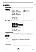
Page 21: ...E II 2 G Ex db eb ia ib mb IIA IIB IIC T6 Ta 60 40 C E II 2 G Ex db eb ia ib mb IIA IIB IIC T5 Ta 60 55 C E II 2 G Ex db eb ia ib mb IIA IIB IIC T4 Ta 60 70 C E II 2 D Ex tb IIIC IP66 T130 C Ta 60 70 C E II 2 D Ex tb IIIC IP66 T95 C Ta 60 55 C E II 2 D Ex tb IIIC IP66 T80 C Ta 60 40 C Certifications and certificates Certificates IECEx ATEX Brazil INMETRO India PESO Russia TR Belarus TR Types of pr...

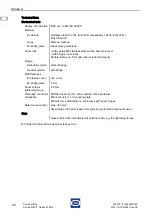
Page 22: ...aptive M6 stainless steel combo head screws or with hinges cam locks Double bit key no 5 for cam lock included in delivery Flange Standard version without flange Special version with flange Wall thickness Enclosure cover min 2 mm Mounting plate 3 mm Cover screws tightening torque 4 5 Nm Protective conductor connection M8 blind rivet nut 1x at the outside of the enclosure M8 rivet nut 1x on mountin...

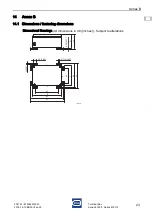
Page 23: ...N EN EN EN EN EN EN EN EN EN EN EN EN EN EN EN Terminal Box Series 8150 1 Series 8150 2 14 Annex B 14 1 Dimensions fastening dimensions Dimensional Drawings All dimensions in mm inches Subject to alterations 12648E00 9 50 0 37 G H E F Ø Ø 7 0 28 7 0 28 b1 c1 c2 b2 a2 a1 D C A B 25 0 98 ...

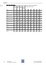
Page 24: ...1 212 8 35 288 11 34 228 8 98 8150 0300 0200 150 1 300 11 81 200 7 87 150 5 91 165 6 50 260 10 24 160 6 30 336 13 23 236 9 29 352 13 86 252 9 92 8150 0360 0176 091 1 360 14 17 176 5 6 95 91 3 58 106 4 17 320 12 60 136 5 35 396 15 59 212 8 35 412 16 22 228 8 98 8150 0360 0360 091 1 360 14 17 360 14 17 91 3 58 106 4 17 320 12 60 320 12 60 396 15 59 396 15 59 412 16 22 412 16 22 8150 0400 0300 150 1 ...

Reviews: