


202161 / 815060300020
2016-12-13·BA00·III·en·05
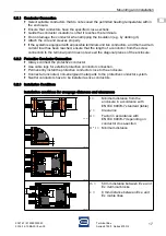
Product selection, project engineering and modification
9
EN
EN
EN
EN
EN
EN
EN
EN
EN
EN
EN
EN
EN
EN
EN
EN
EN
EN
EN
EN
EN
EN
EN
EN
EN
Terminal Box
Series 8150/1, Series 8150/2
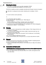
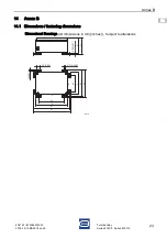
5.1.2 Ascertaining the usable area for cable entries in flange plates
18104E00
Collision frame and earth connection of flange plate
Select a space/area for the cable entry on the flange plate anywhere inside the collision
frame (see thin line in figure). Ensure that screw connections made later do not go beyond
this collision frame.
Observe the following conditions when doing so:
Leave enough distance to the circumferential seal (min. 2 mm) (see detail in figure).
Leave enough distance to the earth connection (min. 10 mm) (see bottom of figure).
5.1.3 Creation of additional drilled holes and through holes by the customer
Modify the device carefully and only in accordance with the safety notes (see chapter 3).
Calculate the usable area, see section 5.1.2.
Create additional through holes by lasing or punching (drilling, hole cutting).
Ensure that the surfaces remain flat during punching and cutting.
Determine the core hole diameter for threads. Do not use an NPT thread!
When determining the through holes, observe the mounting distances.
Adjust the hole diameters to the dimensions of the built-in parts or their seals.
The use of built-in components with flat seal (gasket) is preferred.
Observe section 5.3 "Built-in components" when subsequently equipping components!
5.2
Additional through holes in the enclosure
5.2.1 Creation of additional drilled holes and through holes by R. STAHL
Give the following information to R. STAHL:
- Enclosure side
- Type
- Data sheet
- Quantity, manufacturers and approvals of the components that are to be installed.
Terminal boxes which the customer wants delivered without drilled holes are generally
marked as empty enclosures (marking in accordance with EN IEC 60079-7 and
EN IEC 60079-0, as incomplete equipment "U" inside the enclosure).
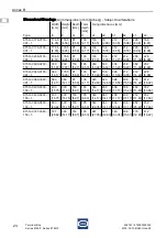
2 [0,08]
10 [0,39]
2 [0,08]


