background image

285616 / 816960300010

2021-11-16·BA00·III·en·00

Commissioning

13

DE
EN

FR

IT

ES

RU

NL

DK

SE

FI

PT

GR

PL

CZ
SK

HU

SL

RO

BG

LV

LT

EE

CH

KR

CN

Cable entry grommet

Series 8169/1

6.1.4 Dismounting

For dismounting, proceed in reverse order to mounting.

6.2

Installation

7

Commissioning

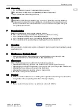
Before commissioning, carry out the following checks:

Check that mounting and installation have been performed correctly.

Check whether the cable entry grommet is damaged.

Check whether the cable entry grommet lies flat against the installation wall.

Check whether all the specified tightening torques have been observed.

8

Operation

During operation, maintenance work (see chapter 9) has to be performed regularly to ensure 

safe functioning.

9

Maintenance, Overhaul, Repair

Observe the relevant national standards and regulations in the country of use, 

e.g. IEC/EN 60079-14, IEC/EN 60079-17, IEC/EN 60079-19.

9.1

Maintenance

Check the following points in addition to the national regulations:

• Whether the cable entry grommet has cracks or other visible signs of damage

• Whether the permissible temperatures are complied with (according to IEC/EN 60079-0)

• Whether the hose clamp and pressure ring fit securely

• Whether the cable entry grommet is free of dust and dirt

• Ensure it is being used as intended.

9.2

Overhaul

Perform overhaul of the device according to the applicable national regulations and the 

safety notes in these operating instructions ("Safety" chapter).

9.3

Repair

Repair work on the device must be performed only by R. STAHL.

Do not mount a cable entry grommet that has been dismounted.

Only mount new cable entry grommets!

Operation under difficult conditions, e.g. on ships in particular, requires additional 

measures to be taken for correct installation, depending on the operating location. 

Further information and instructions on this can be obtained on request from your 

designated sales contact.

Summary of Contents for 8169/1 Series

Page 1: ...Kabeleinführungstülle Reihe 8169 1 Betriebsanleitung Additional languages r stahl com DE EN FR IT ES RU NL DK SE FI PT GR PL CZ SK HU SL RO BG LV LT EE CH KR CN Für künftige Verwendung aufbewahren ...

Page 2: ...leitung 4 2 2 Symbole am Gerät 4 3 Sicherheit 5 3 1 Bestimmungsgemäße Verwendung 5 3 2 Qualifikation des Personals 5 3 3 Restrisiken 6 4 Transport und Lagerung 6 5 Projektierung 7 6 Montage und Installation 9 6 1 Montage Demontage 9 6 2 Installation 13 7 Inbetriebnahme 13 8 Betrieb 13 9 Instandhaltung Wartung Reparatur 13 9 1 Instandhaltung 13 9 2 Wartung 13 9 3 Reparatur 13 10 Rücksendung 14 11 R...

Page 3: ...r oder Benutzer des Geräts weitergeben Betriebsanleitung bei jeder von R STAHL erhaltenen Ergänzung aktualisieren Die Originalbetriebsanleitung ist die deutsche Ausgabe Diese ist rechtsverbindlich in allen juristischen Angelegenheiten 1 3 Weitere Dokumente Datenblatt Dokumente in weiteren Sprachen siehe r stahl com 1 4 Konformität zu Normen und Bestimmungen IECEx ATEX EU Konformitätserklärung und ...

Page 4: ...situation die bei Nichtbeachtung der Sicherheitsmaßnahmen zu schweren Verletzungen führen kann VORSICHT Gefahrensituation die bei Nichtbeachtung der Sicherheitsmaßnahmen zu leichten Verletzungen führen kann HINWEIS Gefahrensituation die bei Nichtbeachtung der Sicherheitsmaßnahmen zu Sachschäden führen kann Symbol Bedeutung 16338E00 Benannte Stelle für Qualitätsüberwachung 02198E00 Gerät gemäß Kenn...

Page 5: ...Zonen 1 und 2 zertifiziert Zur bestimmungsgemäßen Verwendung gehört die Beachtung dieser Betriebsanleitung und der mitgeltenden Dokumente z B der Datenblätter Alle anderen Anwendungen sind nur nach Freigabe der Firma R STAHL bestimmungsgemäß 3 2 Qualifikation des Personals Für die in dieser Betriebsanleitung beschriebenen Tätigkeiten ist eine entsprechend qualifizierte Fachkraft erforderlich Dies ...

Page 6: ...erät auf Beschädigung prüfen Beschädigungen umgehend an R STAHL melden Beschädigtes Gerät nicht montieren und nicht in Betrieb nehmen Unsachgemäße Montage Installation Inbetriebnahme Instandhaltung oder Reinigung Grundlegende Arbeiten wie Montage Installation Inbetriebnahme Instandhaltung oder Reinigung des Geräts dürfen nur nach gültigen nationalen Bestimmungen des Einsatzlandes und von qualifizi...

Page 7: ...e Kabeleinführungstülle plan ist Durchmesser der zu verlegenden Leitung auf den Klemmbereich der Kabeleinführungstülle abstimmen Verwendung einer Zugentlastung der Ausführung B nach DIN EN 62444 Optional kann die Zugentlastung der Fa R STAHL verwendet werden Folgende Abmessungen berücksichtigen Wandstärke alle Maße in mm Zoll 22842E00 Bohrbild Kabeleinführungstülle alle Maße in mm Zoll 22639E00 De...

Page 8: ...1 Positionierung der Zugentlastung optional nur für fest verlegte Leitungen alle Maße in mm Zoll 22644E00 Einbau Zugentlastung Abstand von Kabeleinführungstülle zur Auflagefläche Zugentlastung 22679E00 Bohrbild Zugentlastung alle Maße in mm Zoll 22640E00 Zugentlastung in Flucht zur Leitung Kabeleinführungstülle planen 52 2 05 22 0 86 min 120 4 72 34 1 34 20 0 79 M5 0 20 ...

Page 9: ...ührungstülle Reihe 8169 1 6 Montage und Installation 6 1 Montage Demontage Gerät sorgfältig und nur unter Beachtung der Sicherheitshinweise siehe Kapitel Sicherheit montieren Folgende Einbaubedingungen und Montageanweisungen genau durchlesen und exakt befolgen 6 1 1 Gebrauchslage Kabeleinführungstülle nur in der Grafik gezeigten Position montieren 22693E00 ...

Page 10: ... des Kabel Außendurch messers wählen und an der dafür vorgesehenen Stelle zuschneiden Dabei darauf achten die Klemmfläche nicht zu beschädigen GEFAHR Explosionsgefahr durch zu große oder scharfkantige Bohrung in der Einbauwand Nichtbeachten führt zu tödlichen oder schweren Verletzungen Vor Montage der Kabeleinführungstülle Bohrdurchmesser und Wandstärke kontrollieren Sicherstellen dass die Bohrung...

Page 11: ...Daten 22685E00 Schlauchschelle an der für den Klemmbereich vorgesehenen Position positionieren Abbildung ist beispielhaft dargestellt Leitung durch die Kabeleinführungstülle durchführen Darauf achten dass der Leitungsmantel frei von Verunreinigungen ist Nach Montage prüfen ob Kabeleinführungstülle plan auf der Einbauwand aufliegt und unbeschädigt ist Zulässige Anzugsdrehmomente beachten siehe Tech...

Page 12: ...ende Klemmkomponente auswählen siehe Abbildung Dabei den Klemmbereich der Zugentlastung auf den Durchmesser der zu verlegenden Leitung abstimmen Leitung zwischen Schiene Bügel montieren Darauf achten dass die Schiene bzw der Bügel sauber im Haltebügel aufliegt 22641E00 22642E00 22643E00 Legende A Klemmkomponente mit Durchgangsbohrung B Klemmkomponente mit Gewinde Zulässige Anzugsdrehmomente beacht...

Page 13: ...satzland beachten z B IEC EN 60079 14 IEC EN 60079 17 IEC EN 60079 19 9 1 Instandhaltung Ergänzend zu den nationalen Regeln folgende Punkte prüfen Rissbildung und andere sichtbare Schäden an Kabeleinführungstülle Einhaltung der zulässigen Temperaturen gemäß IEC EN 60079 0 festen Sitz der Schlauchschelle und des Druckrings Kabeleinführungstülle frei von Staub und Verschmutzung Sicherstellen der bes...

Page 14: ...Sie erhalten per E Mail automatisch einen RMA Schein zugeschickt Bitte drucken Sie diese Datei aus Gerät zusammen mit dem RMA Schein in der Verpackung an die R STAHL Schaltgeräte GmbH senden Adresse siehe Kapitel 1 1 11 Reinigung Gerät regelmäßig sanft von Staub und groben Verschmutzungen befreien 12 Entsorgung Nationale und lokal gültige Vorschriften und gesetzliche Bestimmungen zur Entsorgung be...

Page 15: ... IECEx ATEX Technische Daten Umgebungsbedingungen Umgebungs temperatur 35 75 C Die Lagertemperatur entspricht der Umgebungstemperatur Mechanische Daten Schutzart IP66 gemäß IEC EN 60529 Schlagfestigkeit Kategorie 6 gemäß DIN EN 62444 Material Chloropren Kautschuk CR Montage Installation Klemmbereich Klemmbereich Schlauchschelle 22 27 mm Schlauchschelle 25 40 Art Nr 112057 27 33 mm 33 39 mm Schlauc...

Page 16: ... PL CZ SK HU SL RO BG LV LT EE CH KR CN Kabeleinführungstülle Reihe 8169 1 15 Anhang B 15 1 Maßangaben Befestigungsmaße Maßzeichnungen alle Maße in mm Zoll Änderungen vorbehalten 22678E00 22637E00 8169 1 Kabeleinführungstülle optionale Zugentlastung 115 20 4 54 105 4 13 50 1 97 108 4 25 92 3 62 ...

Page 17: ...Cable entry grommet Series 8169 1 Operating instructions Additional languages r stahl com DE EN FR IT ES RU NL DK SE FI PT GR PL CZ SK HU SL RO BG LV LT EE CH KR CN Save for future use ...

Page 18: ...ructions 4 2 2 Symbols on the Device 4 3 Safety 5 3 1 Intended Use 5 3 2 Personnel Qualification 5 3 3 Residual Risks 6 4 Transport and Storage 6 5 Project Engineering 7 6 Mounting and Installation 9 6 1 Mounting Dismounting 9 6 2 Installation 13 7 Commissioning 13 8 Operation 13 9 Maintenance Overhaul Repair 13 9 1 Maintenance 13 9 2 Overhaul 13 9 3 Repair 13 10 Returning the Device 14 11 Cleanin...

Page 19: ... instructions on to each subsequent owner or user of the device Update the operating instructions every time R STAHL issues an amendment The original instructions are the German edition They are legally binding in all legal affairs 1 3 Further Documents Data sheet For documents in other languages see r stahl com 1 4 Conformity with Standards and Regulations IECEx ATEX EU Declaration of Conformity ...

Page 20: ...mplied with WARNING Dangerous situation which can result in severe injuries if the safety measures are not complied with CAUTION Dangerous situation which can result in minor injuries if the safety measures are not complied with NOTICE Dangerous situation which can result in material damage if the safety measures are not complied with Symbol Meaning 16338E00 Notified body for quality control 02198...

Page 21: ...se in hazardous areas of Zones 1 and 2 Intended use includes complying with these operating instructions and the other applicable documents e g the data sheets All other uses are only intended after being approved by R STAHL 3 2 Personnel Qualification Qualified specialist personnel is required to perform the activities described in these operating instructions This primarily applies to work in th...

Page 22: ...mage to R STAHL immediately Do not mount or commission a damaged device Improper mounting installation commissioning maintenance or cleaning Basic work such as mounting installation commissioning maintenance or cleaning of the device must be performed only in accordance with the applicable national regulations of the country of use and only by qualified persons Otherwise the explosion protection m...

Page 23: ... for the cable entry grommet is flat Match the diameter of the conductor to be laid to the clamping range of the cable entry grommet Use version B strain relief in accordance with DIN EN 62444 Optionally strain relief from R STAHL can be used Note the following dimensions Wall thickness All dimensions in mm inch 22842E00 Cable entry grommet drilling hole pattern All dimensions in mm inch 22639E00 ...

Page 24: ...in relief optional only for fixed laid conductors All dimensions in mm inch 22644E00 Installation of strain relief Distance from cable entry grommet to strain relief contact surface 22679E00 Strain relief drilling hole pattern All dimensions in mm inch 22640E00 Design the strain relief so that it is flush with the conductor cable entry grommet 52 2 05 22 0 86 min 120 4 72 34 1 34 20 0 79 M5 0 20 ...

Page 25: ... 8169 1 6 Mounting and Installation 6 1 Mounting Dismounting Mount the device carefully and only in accordance with the safety information see Safety chapter Read through the following installation conditions and assembly instructions carefully and follow them precisely 6 1 1 Operating Position Only mount the cable entry grommet in the position shown in the graphic 22693E00 ...

Page 26: ...er diameter of the cable and cut it to size at the point intended for this purpose When doing so make sure that the clamping surface is not damaged DANGER Explosion hazard because the drilled hole in the installation wall is too large or sharp edged Non compliance results in fatal or severe injuries Before mounting the cable entry grommet check the drilling diameter and wall thickness Make sure th...

Page 27: ...chapter 22685E00 Position the hose clamp at the position intended for the clamping range figure is provided as an example Pass the conductor through the cable entry grommet Make sure that the conductor sleeve is free from contaminants After mounting check whether the cable entry grommet lies flat against the installation wall and is undamaged Observe the permissible tightening torques see Technica...

Page 28: ...E00 Select suitable clamping components see figure When doing so match the clamping range of the strain relief to the diameter of the conductor to be laid Mount the conductor between the bar bracket Make sure that the bar or bracket lies cleanly in the retaining bracket 22641E00 22642E00 22643E00 Legend A clamping component with through hole B clamping component with thread Observe the permissible...

Page 29: ...60079 14 IEC EN 60079 17 IEC EN 60079 19 9 1 Maintenance Check the following points in addition to the national regulations Whether the cable entry grommet has cracks or other visible signs of damage Whether the permissible temperatures are complied with according to IEC EN 60079 0 Whether the hose clamp and pressure ring fit securely Whether the cable entry grommet is free of dust and dirt Ensure...

Page 30: ...t You will automatically receive an RMA form via email Please print this file off Send the device along with the RMA form in the packaging to R STAHL Schaltgeräte GmbH refer to chapter 1 1 for the address 11 Cleaning Regularly wipe or brush the device to remove dust and coarse dirt 12 Disposal Observe national local and statutory regulations regarding disposal Separate materials for recycling Ensu...

Page 31: ...ta Ambient conditions Ambient temperature 35 to 75 C The storage temperature corresponds to the ambient temperature Mechanical data Degree of protection IP66 according to IEC EN 60529 Impact strength Category 6 according to DIN EN 62444 Material Chloroprene rubber CR Mounting installation Clamping range Clamping range Hose clamp 22 to 27 mm Hose clamp 25 to 40 Item no 112057 27 to 33 mm 33 to 39 m...

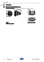
Page 32: ... CZ SK HU SL RO BG LV LT EE CH KR CN Cable entry grommet Series 8169 1 15 Appendix B 15 1 Dimensions Fastening Dimensions Dimensional drawings all dimensions in mm inch Subject to change 22678E00 22637E00 8169 1 Cable entry grommet Optional strain relief 115 20 4 54 105 4 13 50 1 97 108 4 25 92 3 62 ...

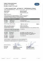
Page 33: ...e CSA Group Netherlands B V Attestation d examen UE de type Utrechtseweg 310 B42 6812AR Arnhem Netherlands NB2813 Produktnormen nach Niederspannungsrichtlinie Product Standards according to Low Voltage Directive Normes des produit pour la Directive Basse Tension EN 62444 2013 2014 30 EU EMV Richtlinie Nicht zutreffend nach Artikel 2 Absatz 2 d 2014 30 EU EMC Directive Not applicable according to a...

Reviews: