background image

203681 / 818660300010

2020-06-23·BA00·III·en·04

General Information 

3

EN
EN
EN
EN
EN
EN
EN
EN
EN
EN
EN
EN
EN
EN
EN
EN
EN
EN
EN
EN
EN
EN
EN
EN
EN

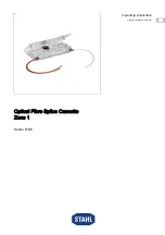
Optical Fibre Splice Cassette Zone 1

Series 8186

1

General Information

1.1

Manufacturer

R. STAHL Schaltgeräte GmbH

Am Bahnhof 30

74638 Waldenburg 

Germany

Phone: +49 7942 943-0

Fax:

+49 7942 943-4333

Internet: r-stahl.com

E-Mail: info@r-stahl.com

1.2

Information regarding the Operating Instructions

ID-No.:

203681 / 818660300010

Publication Code:

2020-06-23·BA00·III·en·04

The original instructions are the German edition.

They are legally binding in all legal affairs.

1.3

Further Documents

• Data sheet

• Data sheet for FO cable (contact manufacturer of FO cable!)

For documents in additional languages, see r-stahl.com.

1.4

Conformity with Standards and Regulations

See certificates and EU Declaration of Conformity: r-stahl.com.

The device has IECEx approval. For certificate please refer to the IECEx homepage:  

http://iecex.iec.ch/

Further national certificates can be downloaded via the following link:  

https://r-stahl.com/en/global/support/downloads/.

Summary of Contents for 8186

Page 1: ...DE DE DE DE DE DE DE DE DE DE DE DE DE DE DE DE DE DE DE DE DE DE DE DE DE Betriebsanleitung Additional languages r stahl com DE Lichtwellenleiter Spleißkassette Zone 1 Reihe 8186 ...

Page 2: ... Sicherheitshinweise 5 3 1 Aufbewahrung der Betriebsanleitung 5 3 2 Qualifikation des Personals 5 3 3 Sichere Verwendung 6 3 4 Umbauten und Änderungen 7 4 Funktion und Geräteaufbau 7 4 1 Funktion 7 4 2 Geräteaufbau 8 5 Technische Daten 8 6 Projektierung 9 7 Transport und Lagerung 9 8 Montage und Installation 9 8 1 Maßangaben Befestigungsmaße 9 8 2 Montage Demontage Gebrauchslage 10 8 3 Installatio...

Page 3: ...0 Publikationsnummer 2020 06 23 BA00 III de 04 Die Originalbetriebsanleitung ist die deutsche Ausgabe Diese ist rechtsverbindlich in allen juristischen Angelegenheiten 1 3 Weitere Dokumente Datenblatt Datenblatt des LWL Kabels Hersteller des LWL Kabels kontaktieren Dokumente in weiteren Sprachen siehe r stahl com 1 4 Konformität zu Normen und Bestimmungen Zertifikate und EU Konformitätserklärung s...

Page 4: ...hr des Schadens Folgen der Gefahr Ergreifen von Gegenmaßnahmen zum Vermeiden der Gefahr bzw des Schadens Symbol Bedeutung Tipps und Empfehlungen zum Gebrauch des Geräts Gefahr durch explosionsfähige Atmosphäre GEFAHR Gefahren für Personen Nichtbeachtung der Anweisung führt zu schweren oder tödlichen Verletzungen bei Personen WARNUNG Gefahren für Personen Nichtbeachtung der Anweisung kann zu schwer...

Page 5: ... Inbetriebnahme Instandhaltung Reparatur Reinigung Fachkräfte die diese Tätigkeiten ausführen müssen einen Kenntnisstand haben der relevante nationale Normen und Bestimmungen umfasst Für Tätigkeiten in explosionsgefährdeten Bereichen sind weitere Kenntnisse erforderlich R STAHL empfiehlt einen Kenntnisstand der in folgenden Normen beschrieben wird IEC EN 60079 14 Projektierung Auswahl und Errichtu...

Page 6: ...te und Bemessungsbetriebs bedingungen auf Typ und Datenschildern sowie die Hinweisschilder am Gerät beachten Vor Installation sicherstellen dass das Gerät unbeschädigt ist Bei Einsatz in Zone 1 oder Zone 2 ist das Gerät in ein schützendes Gehäuse oder einen Schrank entsprechend der IEC EN 60079 0 einzubauen die eine geeignete Schutzart bieten Bei Einsatz in Zone 1 2 und im sicheren Bereich ist ein...

Page 7: ...ßkassette Raum für 2 Spleißschutzhalter Bei Verwendung von 1 Spleißschutzhalter Zubehör Set 203682 können max 6 Lichtwellenleiter bei 2 Spleißschutzhaltern max 12 Lichtwellenleiter aufgenommen werden Mehrere LWL Spleißkassetten dürfen auch übereinander im Stapel installiert werden Dabei muss mindestens die obere LWL Spleißkassette mit dem Deckel abgeschlossen werden GEFAHR Explosionsgefahr durch U...

Page 8: ...halter 6 fach im Zubehör Set 203682 enthalten 5 Schrumpfspleißschutz im Zubehör Set 203682 enthalten 6 Haltenasen Spleißschutzhalter Explosionsschutz Global IECEx Gas und Staub IECEx PTB 10 0060U Ex op pr IIC Gb Europa ATEX Gas und Staub PTB 10 ATEX 2015 U E II 2 G Ex op pr IIC Gb Bescheinigungen und Zertifikate Bescheinigungen IECEx ATEX Technische Daten Umgebungsbedingungen Umgebungs temperatur ...

Page 9: ...ts siehe Kapitel Montage Demontage Gebrauchslage 7 Transport und Lagerung Gerät nur in Originalverpackung transportieren und lagern Gerät trocken keine Betauung und erschütterungsfrei lagern Gerät nicht stürzen 8 Montage und Installation Das Gerät ist für den Einsatz in gasexplosionsgefährdeten Bereichen der Zonen 1 und 2 in staubexplosionsgefährdeten Bereichen der Zonen 21 und 22 sowie auch im si...

Page 10: ...teschaden durch unsachgemäße Montage Nichtbeachten kann Sachschäden verursachen Gerät ausschließlich flach auf Gehäusewand montieren Beschreibung Verwendung 6 Ø 6 0 mm für Gewindestehbolzen M5 Anzugsdrehmoment 0 5 Nm zur Führung und Befestigung der LWL Spleißkassette 7 Ø 2 9 mm für Senkschraube M3 Anzugsdrehmoment 0 5 Nm Verdrehschutz der LWL Spleißkassette 8 Ø 3 5 mm für Schraube M3 Anzugsdrehmom...

Page 11: ...olzen anbringen 21725E00 LWL Spleißkassette mit einem Gewindestehbolzen M5 1 auf der Montage fläche befestigen 21728E00 Um ein Verdrehen der LWL Spleißkassette zu vermeiden zusätzlich mit zwei Senkschrauben M3 1 auf die Montagefläche fixieren 21726E00 Mit der Installation der LWL Fasern fortfahren siehe Kapitel Installation Nach der Installation der LWL Fasern den Deckel aufrasten und mit zwei Sch...

Page 12: ... Spleißkassette mit einem Gewindestehbolzen M5 1 auf der Montage fläche befestigen 21728E00 Um ein Verdrehen der LWL Spleißkassette zu vermeiden zusätzlich mit zwei Senkschrauben M3 1 auf die Montagefläche fixieren 21729E00 Mit der Installation der LWL Fasern fortfahren siehe Kapitel Installation Weitere LWL Spleiß kassette n stapeln 2 und mit der Installation der LWL Fasern fortfahren siehe Kapit...

Page 13: ... abheben Gegebenenfalls Kabelbinder von der Gehäuseseite der LWL Spleißkassette entfernen 21732E00 Gegebenenfalls LWL Fasern aus dem Spleißschutzhalter ausklipsen Gegebenenfalls Spleißschutzhalter ausklipsen dabei die zwei Haltenasen leicht zusammendrücken LWL Fasern aus der LWL Spleißkassette entnehmen 21733E00 Beide Senkschrauben 3 lösen LWL Spleißkassette von der Montagefläche entnehmen 4 Dabei...

Page 14: ...n dass die LWL Spleißkassette unversehrt und sauber ist Sicherstellen dass der angegebene Mindestbiegeradius 35 mm eingehalten wird 8 3 1 Lichtwellenleiter verlegen Innerhalb der LWL Spleißkassette können die Lichtwellenleiter wie folgt verlegt werden 21486E00 Die Lichtwellenleiter dürfen nur mit den zugehörigen Spleißschutzhaltern mit Schrumpfspleißschutz montiert werden Zubehör Set Art Nr 203682...

Page 15: ...0300010 2020 06 23 BA00 III de 04 Montage und Installation 15 DE DE DE DE DE DE DE DE DE DE DE DE DE DE DE DE DE DE DE DE DE DE DE DE DE Lichtwellenleiter Spleißkassette Zone 1 Reihe 8186 21485E00 21484E00 21483E00 ...

Page 16: ...ssungen für Bündeladern 11 und LWL Fasern 12 berücksichtigen siehe Abbildung 03569E00 Bündeladern mit Isolierband umwickeln und mit Kabelbindern an der unteren Gehäuseseite der LWL Spleißkassette befestigen 21752E00 LWL Fasern gemäß den Angaben des Spleißgeräte Herstellers verspleißen Lichtwellenleiter innerhalb der LWL Spleißkassette verlegen siehe Kapitel 8 3 1 Spleißschutzhalter in die Spleißka...

Page 17: ...chtwellenleiter und Kabelbinder in der LWL Spleißkassette 10 Instandhaltung Wartung Reparatur 10 1 Instandhaltung Art und Umfang der Prüfungen den entsprechenden nationalen Vorschriften entnehmen Prüfungsintervalle an Betriebsbedingungen anpassen Bei der Instandhaltung des Geräts mindestens folgende Punkte prüfen fester Sitz der untergeklemmten Leitungen Rissbildung und andere sichtbare Schäden am...

Page 18: ...der Verpackung an die R STAHL Schaltgeräte GmbH senden Adresse siehe Kapitel 1 1 11 Reinigung Zur Vermeidung elektrostatischer Aufladung dürfen die Geräte in explosionsgefährdeten Bereichen nur mit einem feuchten Tuch gereinigt werden Bei feuchter Reinigung Wasser oder milde nicht scheuernde nicht kratzende Reinigungsmittel verwenden Keine aggressiven Reinigungsmittel oder Lösungsmittel verwenden ...

Page 19: ...EN EN EN EN EN EN EN EN EN EN EN EN EN EN EN EN EN EN EN EN EN EN EN EN EN Operating instructions Additional languages r stahl com EN Optical Fibre Splice Cassette Zone 1 Series 8186 ...

Page 20: ...ls on the Device 5 3 Safety Notes 5 3 1 Operating Instructions Storage 5 3 2 Personnel Qualification 5 3 3 Safe Use 6 3 4 Modifications and Alterations 7 4 Function and Device Design 7 4 1 Function 7 4 2 Device Design 8 5 Technical Data 8 6 Engineering 9 7 Transport and Storage 9 8 Mounting and Installation 9 8 1 Dimensions Fastening Dimensions 9 8 2 Mounting Dismounting Operating Position 10 8 3 ...

Page 21: ...ns ID No 203681 818660300010 Publication Code 2020 06 23 BA00 III en 04 The original instructions are the German edition They are legally binding in all legal affairs 1 3 Further Documents Data sheet Data sheet for FO cable contact manufacturer of FO cable For documents in additional languages see r stahl com 1 4 Conformity with Standards and Regulations See certificates and EU Declaration of Conf...

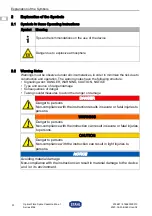
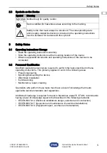
Page 22: ...G CAUTION NOTICE Type and source of danger damage Consequences of danger Taking countermeasures to avoid the danger or damage Symbol Meaning Tips and recommendations on the use of the device Danger due to explosive atmosphere DANGER Danger to persons Non compliance with the instruction results in severe or fatal injuries to persons WARNING Danger to persons Non compliance with the instruction can ...

Page 23: ...ng the device Electrical Installation Commissioning Maintenance repair cleaning Specialists who perform these tasks must have a level of knowledge that meets applicable national standards and regulations Additional knowledge is required for tasks in hazardous areas R STAHL recommends having a level of knowledge equal to that described in the following standards IEC EN 60079 14 Electrical installat...

Page 24: ...ions on the rating data and information plates located on the device Before installation make sure that the device is not damaged When used in Zone 1 or Zone 2 the device is to be installed in a protective enclosure or in a cabinet that offers a suitable degree of protection in accordance with IEC EN 60079 0 An enclosure with a protection rating of at least IP54 is required for use in Zones 1 and ...

Page 25: ...ssette provides space for 2 splice protector holders When using 1 splice protector holder accessories set 203682 a max of 6 fibre optics can be installed or max 12 fibre optics with 2 splice protector holders Multiple FO splice cassettes can also be installed on top of one another in a stack In this case at least the upper FO splice cassette must be closed using the cover DANGER Explosion hazard d...

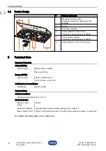
Page 26: ...luded in accessories set 203682 5 Shrink splice protector Included in accessories set 203682 6 Splice protector holder retaining lug Explosion Protection Global IECEx Gas and dust IECEx PTB 10 0060U Ex op pr IIC Gb Europe ATEX Gas and dust PTB 10 ATEX 2015 U E II 2 G Ex op pr IIC Gb Certifications and certificates Certificates IECEx ATEX Technical Data Ambient conditions Ambient temperature 55 to ...

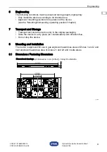
Page 27: ...ice see the Mounting dismounting operating position chapter 7 Transport and Storage Transport and store the device only in the original packaging Store the device in a dry place no condensation and vibration free Do not drop the device 8 Mounting and Installation The device is approved for use in gas explosion hazardous areas of Zones 1 and 2 and dust explosion hazardous area of Zones 21 and 22 an...

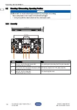
Page 28: ...ce damage caused by improper mounting Non compliance can result in material damage Only mount the device flat on the enclosure wall Description Use 6 Dia 6 0 mm for threaded studs M5 tightening torque 0 5 Nm For guiding and mounting the FO splice cassette 7 Dia 2 9 mm for countersunk head screw M3 tightening torque 0 5 Nm Anti twist protection for FO splice cassette 8 Dia 3 5 mm for screw M3 tight...

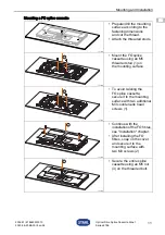
Page 29: ...d Attach the threaded studs 21725E00 Mount the FO splice cassette using an M5 threaded stud 1 on the mounting surface 21728E00 To avoid twisting the FO splice cassette secure it to the mounting surface with two additional M3 countersunk head screws 1 21726E00 Continue with the installation of the FO fibres see Installation chapter After installing the FO fibres snap on the cover and secure it to t...

Page 30: ... 21725E00 Mount the FO splice cassette using an M5 threaded stud 1 on the mounting surface 21728E00 To avoid twisting the FO splice cassette secure it to the mounting surface with two additional M3 countersunk head screws 1 21729E00 Continue with the installation of the FO fibres see Installation chapter Stack additional FO splice cassettes 2 and continue with the installation of the FO fibres see...

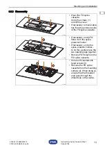
Page 31: ...ecessary remove cable ties from the enclosure side of the FO splice cassette 21732E00 If necessary unclip FO fibres from the splice protector holder If necessary unclip the splice protector holder to do this gently press the two retaining lugs together Remove FO fibres from the FO splice cassette 21733E00 Undo both countersunk head screws 3 Remove the FO splice cassette from the mounting surface 4...

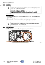
Page 32: ... the FO splice cassette is clean and undamaged Ensure that the specified minimum bend radius 35 mm is complied with 8 3 1 Laying Fibre Optics Inside the FO splice cassette the fibre optics can be laid as follows 21486E00 The fibre optics must only be installed with the associated splice protector holders with shrink splice protector Accessories set item no 203682 1 x splice protector holder 6 x sh...

Page 33: ...0300010 2020 06 23 BA00 III en 04 Mounting and Installation 15 EN EN EN EN EN EN EN EN EN EN EN EN EN EN EN EN EN EN EN EN EN EN EN EN EN Optical Fibre Splice Cassette Zone 1 Series 8186 21485E00 21484E00 21483E00 ...

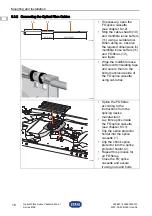
Page 34: ...for multifibre loose buffers 11 and FO fibres 12 see figure 03569E00 Wrap the multifibre loose buffers with insulating tape and secure them to the bottom enclosure side of the FO splice cassette using cable ties 21752E00 Splice the FO fibres according to the instructions from the splicing device manufacturer Lay fibre optics inside the FO splice cassette see chapter 8 3 1 Clip the splice protector...

Page 35: ...e FO splice cassette 10 Maintenance Overhaul Repair 10 1 Maintenance Consult the relevant national regulations to determine the type and extent of inspections Adapt inspection intervals to the operating conditions During maintenance of the device check at least whether the clamping screws holding the electric lines are securely seated whether the device enclosure and or protective enclosure have c...

Page 36: ... STAHL Schaltgeräte GmbH refer to chapter 1 1 for the address 11 Cleaning To avoid electrostatic charging the devices located in potentially explosive areas may only be cleaned using a damp cloth When cleaning with a damp cloth use water or mild non abrasive non scratching cleaning agents Do not use aggressive detergents or solvents 12 Disposal Observe national and local regulations and statutory ...

Page 37: ...Standard s Norme s 2014 34 EU ATEX Richtlinie 2014 34 EU ATEX Directive 2014 34 UE Directive ATEX ENIEC 60079 0 2018 EN 60079 28 2015 Kennzeichnung marking marquage II2 G Ex op pr IIC Gb NB0158 EU Baumusterprüfbescheinigung EU Type Examination Certificate Attestation d examen CE UE de type PTB 10 ATEX 2015 U Physikalisch Technische Bundesanstalt Bundesallee 100 38116 Braunschweig Germany NB0102 20...

Reviews: