background image

Montage und Installation

12

226774 / 8188601300

2016-04-05·BA00·III·de·04

Sammelschienensystem

Reihe 8188

DE
DE
DE
DE
DE
DE
DE
DE
DE
DE
DE
DE
DE
DE
DE
DE
DE
DE
DE
DE
DE
DE
DE
DE
DE

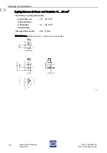
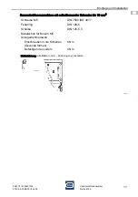
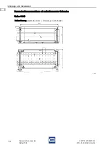
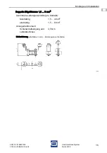
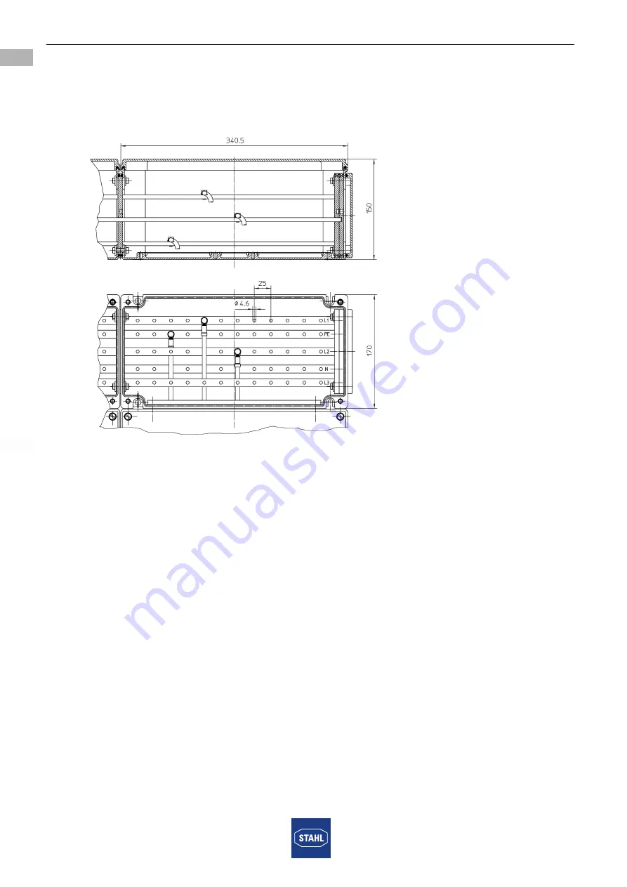
Sammelschienenanschluss mit selbstformender Schraube

Reihe 8146

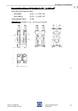
Maßzeichnung (alle Maße in mm) – Änderungen vorbehalten

16151E00

Summary of Contents for 8188 1 Series

Page 1: ...DE EN DE EN DE EN DE EN DE EN DE EN DE EN DE EN DE Betriebsanleitung Operating instructions Additional languages www stahl ex com DE EN Sammelschienensystem Busbar system Reihe 8188 Series 8188...

Page 2: ......

Page 3: ...DE DE DE DE DE DE DE DE DE DE DE DE DE DE DE DE DE DE DE DE DE DE DE DE DE Betriebsanleitung Additional languages www stahl ex com DE Sammelschienensystem Reihe 8188...

Page 4: ...bsanleitung 3 2 2 Warnhinweise 4 2 3 Symbole am Ger t oder in Schaltpl nen 4 3 Sicherheitshinweise 5 3 1 Aufbewahrung der Betriebsanleitung 5 3 2 Sichere Verwendung 5 3 3 Umbauten und nderungen 5 4 Fu...

Page 5: ...8601300 Publikationsnummer 2016 04 05 BA00 III de 04 Die Originalbetriebsanleitung ist die englische Ausgabe Diese ist rechtsverbindlich in allen juristischen Angelegenheiten 1 3 Weitere Dokumente Dat...

Page 6: ...m Vermeiden der Gefahr des Schadens 2 3 Symbole am Ger t GEFAHR Gefahren f r Personen Nichtbeachtung der Anweisung f hrt zu schweren oder t dlichen Verletzungen bei Personen WARNUNG Gefahren f r Perso...

Page 7: ...m Personal durchf hren lassen Bei Installation und im Betrieb die Angaben Kennwerte und Bemessungsbetriebsbedingungen auf Typ und Datenschildern sowie die Hinweisschilder am Ger t beachten Bei Betrieb...

Page 8: ...2G Ex e IIC Gb E I M2 Ex e I Mb Bescheinigungen und Zertifikate Bescheinigungen IECEx ATEX Technische Daten Elektrische Daten Bemessungs betriebsspannung Ue 750 V Bemessungs isolationsspannung Ui 630...

Page 9: ...zel schienensystem 400 A 8188 2 Doppel schienensystem 630 A Elektrische Daten Bemessungs betriebsstrom max 200 A max 400 A max 630 A Bemessungs kurzschlussstrom bei St tzabstand Bemessungs kurzzeitstr...

Page 10: ...nur in Originalverpackung transportieren und lagern Ger t trocken keine Betauung und ersch tterungsfrei lagern Ger t nicht st rzen Technische Daten Ausf hrung 8188 2 Geh usereihe 8146 8188 3 Geh usere...

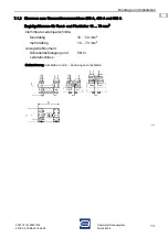
Page 11: ...DE DE DE DE DE DE 7 Montage und Installation 7 1 Ma angaben Befestigungsma e 7 1 1 Klemmen zum Stromschienenanschluss 160 A 12 x 6 mm Zugb gelklemme f r Rund und Flachleiter 16 95 mm2 klemmbare Leiter...

Page 12: ...DE DE DE DE DE DE DE DE DE DE DE DE DE DE DE DE DE DE DE DE DE DE DE Zugb gelklemme f r Rund und Flachleiter 10 25 mm2 klemmbare Leiterquerschnitte feindr htig mit Aderendh lse 10 16 mm2 Sektorleiter...

Page 13: ...DE DE DE DE DE DE DE DE DE Sammelschienenanschluss mit selbstformender Schraube bis 16 mm2 Schraube M5 DIN 7500 ISO 4017 Federring DIN 128 5 Scheibe DIN 125 5 3 Kabelschuh f r Bolzen M5 Anzugsdrehmom...

Page 14: ...04 05 BA00 III de 04 Sammelschienensystem Reihe 8188 DE DE DE DE DE DE DE DE DE DE DE DE DE DE DE DE DE DE DE DE DE DE DE DE DE Sammelschienenanschluss mit selbstformender Schraube Reihe 8146 Ma zeich...

Page 15: ...DE DE DE DE DE DE DE DE DE DE DE DE 7 1 2 Klemmen zum Stromschienenanschluss 200 A 400 A und 630 A Zugb gelklemme f r Rund und Flachleiter 10 70 mm2 klemmbare Leiterquerschnitte feindr htig 10 50 mm2...

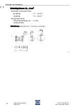
Page 16: ...8 DE DE DE DE DE DE DE DE DE DE DE DE DE DE DE DE DE DE DE DE DE DE DE DE DE Einfachb gelklemme 1 5 6 mm2 klemmbare Leiterquerschnitte feindr htig 1 5 4 mm2 eindr htig 1 5 6 mm2 Anzugsdrehmoment Schie...

Page 17: ...DE DE DE DE DE DE DE DE DE DE DE DE DE DE DE DE DE DE DE DE DE DE DE Doppelte B gelklemme 1 5 6 mm2 klemmbare Leiterquerschnitte pro Kontakt feindr htig 1 5 4 mm2 eindr htig 1 5 6 mm2 Anzugsdrehmomen...

Page 18: ...Reihe 8188 DE DE DE DE DE DE DE DE DE DE DE DE DE DE DE DE DE DE DE DE DE DE DE DE DE Sammelschienenklemme f r Rundleiter 50 240 mm2 klemmbare Leiterquerschnitte feindr htig 50 185 mm2 mehrdr htig 50...

Page 19: ...DE DE DE DE DE DE DE DE DE DE DE DE DE DE DE DE DE DE DE DE DE DE DE DE DE Sammelschienenklemme f r Rundleiter 2 x 50 2 x 240 mm2 klemmbare Leiterquerschnitte feindr htig 2 x 50 2 x 185 mm2 mehrdr hti...

Page 20: ...schienensystem Reihe 8188 DE DE DE DE DE DE DE DE DE DE DE DE DE DE DE DE DE DE DE DE DE DE DE DE DE Sammelschienenklemme f r Flachleiter 11 x 21 x 1 mm klemmbare Leiter Flachband 11 x 21 x 1 mm Anzug...

Page 21: ...achleiter 11 x 21 x 1 mm Zugb gelklemme f r Rundleiter 35 240 mm2 Zugb gelklemme f r Flachleiter 11 x 21 x 1 mm klemmbarer Leiterquerschnitt a feindr htig 35 120 mm2 mehrdr htig 35 150 mm2 b feindr ht...

Page 22: ...oder Gewicht des Sammelschienensystems entnehmen Sie der beiliegenden Aufbauzeichnung Beim Einbau gesondert bescheinigter Ger te in Geh usedeckel und oder auf Montageplatten beachten dass die mechani...

Page 23: ...schritten werden Stellen Sie beim Abisolieren sicher dass die Leiterisolation bis an die Klemmen heranreicht Besch digen Sie den Leiter beim Abisolieren nicht Beachten Sie die Angaben zu den Klemmen i...

Page 24: ...gen den entsprechenden nationalen Vorschriften entnehmen Pr fungsintervalle an Betriebsbedingungen anpassen maximal jedoch alle drei Jahre Bei der Instandhaltung des Ger ts muss Folgendes gepr ft werd...

Page 25: ...chten Materialien getrennt dem Recycling zuf hren Umweltgerechte Entsorgung aller Bauteile gem den gesetzlichen Bestimmungen sicherstellen 11 Zubeh r und Ersatzteile GEFAHR Gefahr durch unsachgem e Wa...

Page 26: ...EN EN EN EN EN EN EN EN EN EN EN EN EN EN EN EN EN EN EN EN EN EN EN EN EN Operating instructions Additional languages www stahl ex com EN Busbar system Series 8188...

Page 27: ...ols in these Operating Instructions 3 2 2 Warning Notes 4 2 3 Symbols on the Device 4 3 Safety Notes 5 3 1 Operating Instructions Storage 5 3 2 Safe Use 5 3 3 Modifications and Alterations 5 4 Functio...

Page 28: ...structions ID No 226774 8188601300 Publication Code 2016 04 05 BA00 III en 04 The original instructions are the English edition They are legally binding in all legal affairs 1 3 Further Documents Data...

Page 29: ...nger Taking countermeasures to avoid the danger damage 2 3 Symbols on the Device DANGER Danger for persons Non compliance with the instruction results in severe or fatal injuries to persons WARNING Da...

Page 30: ...ained personnel During installation and operation observe the information characteristic values and rated operating conditions on the rating data and information plates located on the device Always co...

Page 31: ...Gb E I M2 Ex e I Mb Certifications and certificates Certificates IECEx ATEX Technical Data Electrical data Rated operational voltage Ue 750 V Rated insulation voltage Ui 630 V Rated impulse withstand...

Page 32: ...ystem 400 A 8188 2 double busbar system 630 A Electrical data Rated operational current max 200 A max 400 A max 630 A Rated short circuit current at supporting distance Rated short time current 1s at...

Page 33: ...e the device only in the original packaging Store the device in a dry place no condensation and vibration free Do not drop the device Technical Data Version 8188 2 enclosure Series 8146 8188 3 enclosu...

Page 34: ...Mounting and Installation 7 1 Dimensions Fastening Dimensions 7 1 1 Terminals for Busbar Connection 160 A 12 x 6 mm U clamp terminal for round and flat conductors 16 95 mm2 Clampable conductor cross s...

Page 35: ...EN EN EN EN EN EN EN EN EN EN EN EN EN EN EN U clamp terminal for round and flat conductors 10 25 mm2 Clampable conductor cross sections finely stranded with core end sleeve 10 16 mm2 stranded sector...

Page 36: ...EN EN EN EN EN EN EN EN EN EN Busbar connection with self tapping screw up to 16 mm2 M5 screw DIN 7500 ISO 4017 Split washer DIN 128 5 Washer DIN 125 5 3 Cable lug for M5 bolt Tightening torques Screw...

Page 37: ...04 05 BA00 III en 04 Busbar system Series 8188 EN EN EN EN EN EN EN EN EN EN EN EN EN EN EN EN EN EN EN EN EN EN EN EN EN Busbar connection with self tapping screw Series 8146 Dimensional Drawings al...

Page 38: ...EN EN EN EN EN EN EN 7 1 2 Terminals for Busbar Connection 200 A 400 A and 630 A U clamp terminal for round and flat conductors 10 70 mm2 Clampable conductor cross sections finely stranded 10 50 mm2 s...

Page 39: ...EN EN EN EN EN EN EN EN EN EN EN EN EN EN EN EN EN EN EN EN EN Single U clamp terminal 1 5 6 mm2 clampable conductor cross sections finely stranded 1 5 4 mm2 solid 1 5 6 mm2 Tightening torque Bar fast...

Page 40: ...EN EN EN EN EN EN EN EN EN EN EN EN EN EN EN EN EN EN EN Double U clamp terminal 1 5 6 mm2 clampable conductor cross sections per contact finely stranded 1 5 4 mm2 solid 1 5 6 mm2 Tightening torque Ba...

Page 41: ...EN EN EN EN EN EN EN EN EN EN EN EN EN EN EN EN EN EN EN EN EN EN EN EN Busbar terminal for round conductors 50 240 mm2 clampable conductor cross sections finely stranded 50 185 mm2 stranded 50 240 m...

Page 42: ...EN EN EN EN EN EN EN EN EN EN EN EN EN EN EN EN EN EN EN EN Busbar terminal for round conductors 2 x 50 2 x 240 mm2 clampable conductor cross sections finely stranded 2 x 50 2 x 185 mm2 stranded 2 x...

Page 43: ...Series 8188 EN EN EN EN EN EN EN EN EN EN EN EN EN EN EN EN EN EN EN EN EN EN EN EN EN Busbar terminal for flat conductors 11 x 21 x 1 mm Clampable conductors Ribbon cable 11 x 21 x 1 mm Tightening t...

Page 44: ...m U clamp terminal for round conductors 35 240 mm2 U clamp terminal for flat conductors 11 x 21 x 1 mm Clampable conductor cross section a finely stranded 35 120 mm2 stranded 35 150 mm2 b finely stran...

Page 45: ...dimensions or weight of the busbar system can be found in the enclosed assembly drawing During installation of specially certified devices in enclosure cover and or on mounting plates ensure that the...

Page 46: ...nd means of running them When removing the insulation make sure that the conductor insulation reaches up to the terminals Do not damage the conductor when removing the insulation Observe the specifica...

Page 47: ...to determine the type and extent of inspections Adapt inspection intervals to the operating conditions however maximum every three years During maintenance of the device the following must be checked...

Page 48: ...when sending it for recycling Ensure environmentally friendly disposal of all components according to the statutory regulations 11 Accessories and Spare Parts DANGER Danger due to improper maintenanc...

Page 49: ......

Reviews: