background image

253215 / 941960310090

2017-04-21·BA00·III·en·01

Parameterization and Commissioning  

27

EN
EN
EN
EN
EN
EN
EN
EN
EN
EN
EN
EN
EN
EN
EN
EN
EN
EN
EN
EN
EN
EN
EN
EN
EN

Bus-Carrier for linking device

Series 9419/0..-LD1-..E1

9.1

DIP Switch on the bus-Carrier

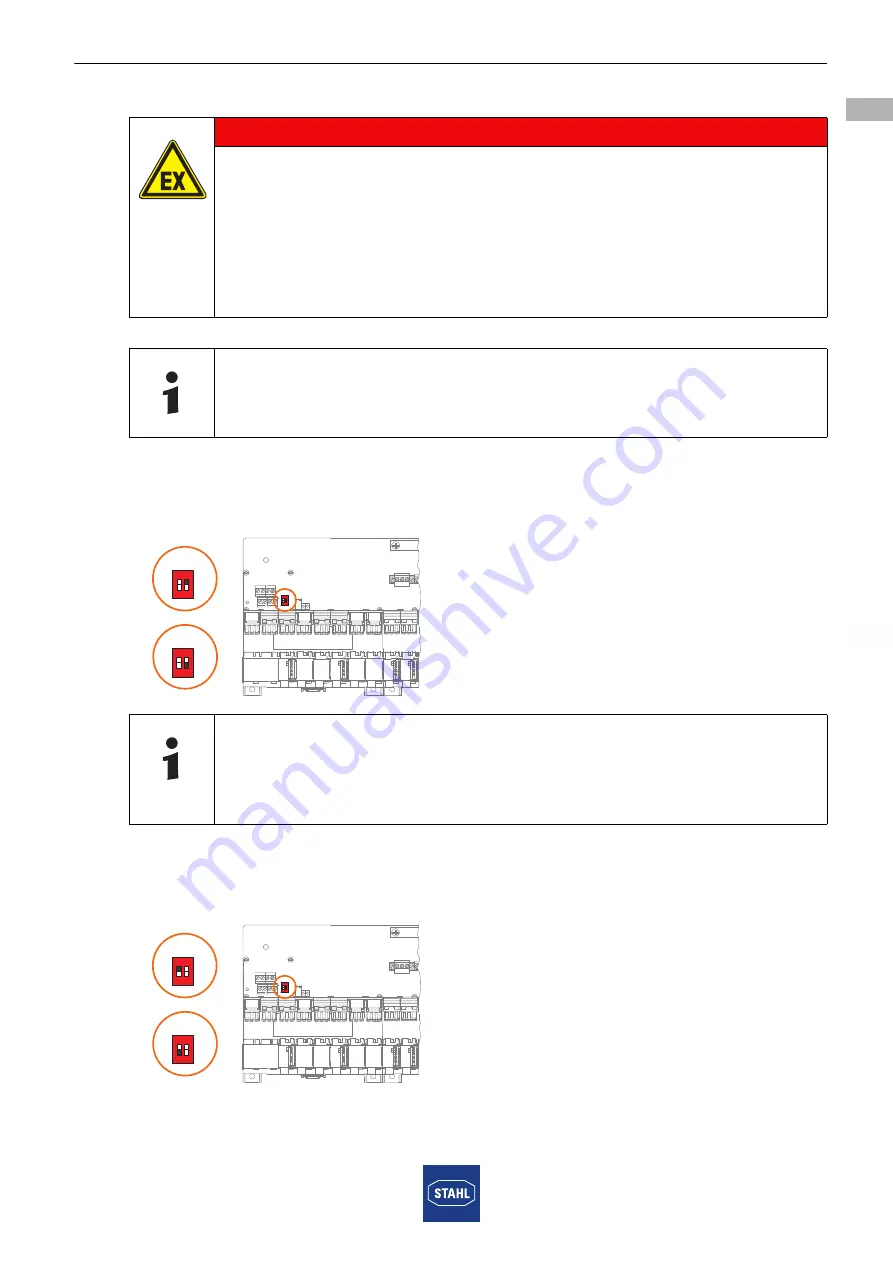
9.1.1 DIP Switch "RED" – Redundant Auxiliary Power

On delivery, the redundant auxiliary power is active.

The "RED" DIP switch is in the "ON" position in this case.

18041E00

9.1.2 "DIA" DIP Switch - Error Contact

On delivery, the error contact is active.

The "DIA" DIP switch is in the "ON" position in this case.

18087E00

DANGER

Explosion hazard when configuring parameters or switching the  

DIP switch in Zone 2!

Non-compliance results in severe or fatal injuries.

• Ensure that the device is de-energised before configuring  

parameters or switching the DIP switch. Settings on the DIP switch 

are permitted at any time in the de-energized state or with a hot 

work permit.

The "RED" or "DIA" designation of the DIP switch refers to the "ON"  

PCB label.

For a simplex auxiliary power supply, set the "RED" DIP switch to "OFF".  

Otherwise the lack of a redundant auxiliary power supply is reported as an  

error.

Dia

red

1

2

Dia

red

1

2

1

2

ON

ON

Dia

red

1

2

O
N

Dia

red

1

2

O
N

1

2

ON

ON

Summary of Contents for 9419/0 LD1 E1 Series

Page 1: ...DE EN DE EN DE EN DE EN DE EN DE Betriebsanleitung Operating instructions Additional languages www stahl ex com DE EN bus Träger für Linking Device Bus Carrier for linking device Reihe 9419 0 LD1 E1 Series 9419 0 LD1 E1 ...

Page 2: ......

Page 3: ...DE DE DE DE DE DE DE DE DE DE DE DE DE DE DE DE DE DE DE DE DE DE DE DE DE Betriebsanleitung Additional languages www stahl ex com DE bus Träger für Linking Device Reihe 9419 0 LD1 E1 ...

Page 4: ...bauten und Änderungen 7 4 Funktion und Geräteaufbau 7 4 1 Funktion 7 4 2 Geräteaufbau 10 5 Technische Daten 11 6 Projektierung 13 6 1 Maximal zulässige Umgebungstemperaturen ohne Zwangsbelüftung 13 6 2 Einbaulage 14 6 3 Weitere Projektierungsdokumente 16 7 Transport und Lagerung 16 8 Montage und Installation 16 8 1 Maßangaben Befestigungsmaße 17 8 2 Montage Demontage Gebrauchslage 17 8 3 Installat...

Page 5: ...leitung ist die englische Ausgabe Diese ist rechtsverbindlich in allen juristischen Angelegenheiten 1 3 Weitere Dokumente Betriebsanleitungen 9412 9415 Linking Device FG 200 HSE FF der Fa Softing Datenblatt 9419 9412 9415 Linking Device FG 200 HSE FF der Fa Softing Dokumentation zum Linking Device FG 200 HSE FF siehe http industrial softing com Weitere Sprachen siehe www stahl ex com 1 4 Konformit...

Page 6: ...hr des Schadens Folgen der Gefahr Ergreifen von Gegenmaßnahmen zum Vermeiden der Gefahr bzw des Schadens Symbol Bedeutung Tipps und Empfehlungen zum Gebrauch des Geräts Gefahr durch explosionsfähige Atmosphäre GEFAHR Gefahren für Personen Nichtbeachtung der Anweisung führt zu schweren oder tödlichen Verletzungen bei Personen WARNUNG Gefahren für Personen Nichtbeachtung der Anweisung kann zu schwer...

Page 7: ...ebnahme Instandsetzung Reparatur Reinigung Fachkräfte die diese Tätigkeiten ausführen müssen einen Kenntnisstand haben der relevante nationale Normen und Bestimmungen umfasst Für Tätigkeiten in explosionsgefährdeten Bereichen sind weitere Kenntnisse erforderlich R STAHL empfiehlt einen Kenntnisstand der in folgenden Normen beschrieben wird IEC EN 60079 14 Projektierung Auswahl und Errichtung elekt...

Page 8: ...Bei Betrieb in explosionsgefährdeten Bereichen der Zone 2 muss der bus Träger 9419 in ein Gehäuse eingebaut werden das den Anforderungen der IEC EN 60079 15 entspricht Bei Einsatz in explosionsgefährdeten Bereichen sind keine Anschlussarbeiten und kein Abnehmen Aufstecken von Geräten zulässig Ausnahme Es liegt eine Heißarbeitsgenehmigung vor oder das ganze System ist spannungsfrei geschaltet Die m...

Page 9: ...n Feldbus Stromversorgungen mit Hilfsenergie simplex oder redundant Zur Meldung von Leitungsfehlern und Hilfsenergieausfall über Meldekontakte am bus Träger Die aufgesteckten Geräte FPS LD werden über den Träger mit Hilfsenergie versorgt und untereinander sowie mit den am bus Träger angeordneten Feldbusanschlüssen und Ethernet LD verbunden GEFAHR Explosionsgefahr durch Umbauten und Änderungen am G...

Page 10: ...Diagnoseinformationen der einzelnen Segmente Advanced Physical Layer Parameter aus den FPS Geräten im Träger auszulesen um Diagnoseinformationen über ein Segment am bus Träger oder ein separates Diagnosesegment an das Leitsystem zu übertragen Folgende bus Träger für das Linking Device sind derzeit erhältlich 9419 04F LD1 01E1 simplex Spannungsversorgung FPS von 4 Feldbus Segmenten und 1 Linking De...

Page 11: ...ing Device red 18322E00 Arbeitsweise Der bus Träger Typ 9419 0 LD1 E1 verfügt zusätzlich zu den Steckplätzen für 4 bzw 8 Feldbus Power Supply FPS Typ 9412 und einem Diagnose Kommunikations Modul DCM Typ 9415 über einen bzw zwei Steckplätz e für das Linking Device LD Typ FG 200 Fa Softing Das Linking Device dient als Gateway zwischen FOUNDATION fieldbus H1 FF H1 und FOUNDATION fieldbus High Speed E...

Page 12: ... connection 6 Schirmschiene für Klemmbügel Zubehörteile Schirmauflage der Segmentleitung Klemmbügel als Zubehör erhältlich 113509 Optional kann der Schirm der Segmentleitung an die Schirmklemme S der Feldbusklemme angeschlossen werden 7 Schirmsammel Klemme PA shield Potentialausgleich PA shield Gemeinsamer Verbindungspunkt von Schirmschiene und Schirmklemmen S 8 Steckplätze für Linking Device auf ...

Page 13: ...e jeweilige Bescheinigung und Betriebsanleitung Technische Daten Elektrische Daten Hilfsenergie Nennspannung UN 24 V DC Nennstrom IN 8 A Spannungs bereich 19 32 V Restwelligkeit innerhalb des Spannungs bereichs 3 6 VSS Redundante Einspeisung ja diodenentkoppelt Verpolschutz ja Betriebsanzeige 2 LED grün pri red Elektromagnetische Verträglichkeit Geprüft nach folgenden Normen und Vorschriften EN 61...

Page 14: ...h durch Einrasten am vorgesehenen Steckplatz Ethernet HSE Modbus TCP durch RJ45 Stecker DCM siehe Betriebsanleitung 9415 Schirm Schirmklemme oder Steckverbinder oder Schirmschiene mit Zugentlastung Anschluss querschnitt Montageart auf Hutschiene NS35 15 NS35 7 5 oder Montageplatte Schrauben M5 Drehmoment 2 7 Nm Einbaulage senkrecht oder waagrecht Schutzart IP00 Klemmen IP20 Gehäusematerial PA 6 6 ...

Page 15: ... einer Feldbus Stromversorgung Beim redundanten Betrieb wird ein Segment von zwei Feldbus Stromversorgungen gemeinsam versorgt wobei der Laststrom jedes Moduls halbiert wird Zum Ermitteln der maximal zulässigen Umgebungstemperatur muss daher in den Diagrammen für den Strom Iout der halbe Strombedarf des Segments eingesetzt werden Beim bus Träger Typ 9419 0 LD1 E1 mit Steckplatz für Linking Device ...

Page 16: ...II de 01 bus Träger für Linking Device Reihe 9419 0 LD1 E1 DE DE DE DE DE DE DE DE DE DE DE DE DE DE DE DE DE DE DE DE DE DE DE DE DE 6 2 Einbaulage 6 2 1 Waagerechte Einbaulage 18018E00 18019E00 18043E00 Typ Spannung V DC 9412 00 30 9412 01 17 9412 02 24 ...

Page 17: ...1 Projektierung 15 DE DE DE DE DE DE DE DE DE DE DE DE DE DE DE DE DE DE DE DE DE DE DE DE DE bus Träger für Linking Device Reihe 9419 0 LD1 E1 6 2 2 Senkrechte Einbaulage 18020E 18021E00 1804400 Typ Spannung V DC 9412 00 30 9412 01 17 9412 02 24 ...

Page 18: ... entsprechende Betriebsanleitung GEFAHR Explosionsgefahr bei Installation ohne Feldgehäuse Nichtbeachten führt zu schweren oder tödlichen Verletzungen Bei Einsatz in Zone 2 ist das Gerät in ein Gehäuse einzubauen das die Anforderungen der IEC EN 60079 15 erfüllt GEFAHR Explosionsgefahr durch falsche Installation des Geräts Nichtbeachten führt zu schweren oder tödlichen Verletzungen Installation st...

Page 19: ...ene Maßzeichnung alle Maße in mm Zoll Änderungen vorbehalten 18231E00 Der Betrieb des bus Trägers ist nur in folgenden Einbaulagen zulässig Einbau senkrecht oder waagrecht siehe auch Kapitel Projektierung 18027E00 18028E00 bus Träger auf Hutschiene entsprechend IEC EN 60715 Typ NS 35 7 5 oder NS 35 15 ansetzen 1 und so aufschwenken dass der Fußriegel bzw die beiden Fußriegel einrasten 2 X 62 2 30 ...

Page 20: ...tände siehe Kapitel Maßangaben Befestigungsmaße Vor der Montage der Feldbus Stromversorgung müssen alle Klemmen und Abdeckungen auf der Seite des Fußriegels entfernt werden Beim Aufschwenken des Geräts auf den bus Träger darauf achten dass das Gehäuse der Feldbus Stromversorgung nicht verkantet 10859E00 Abdeckung an der obersten Klemme sowie schwarze und grüne Schraubklemmen am Gerät auf der Seite...

Page 21: ...Träger aufschwenken 1 Gerät bis zum roten Rasthebel einschwenken Sicherstellen dass der rote Rasthebel in die Aussparung des Geräts greift 2 Roten Rasthebel und Gerät gegeneinander drücken bis der Rasthebel hörbar einrastet 18031E00 Gerät am entsprechenden Steckplatz ansetzen und auf bus Träger aufschwenken 1 Gerät bis zum roten Doppel Rasthebel einschwenken Sicherstellen dass der rote Doppel Rast...

Page 22: ...iene Das Diagnose Kommunikations Modul DCM wird auf den Montageplatz rechts von den Feldbus Stromversorgungen auf den bus Träger montiert 18034E00 Flachbandkabel zuerst am bus Träger einstecken Das Modul mit der oberen Nut in das Tragschienenprofil am Montageplatz einhängen Modul nach unten schwenken bis der Fußriegel einrastet Flachbandkabel am DCM vorsichtig einstecken 18035E00 18036E00 Mit eine...

Page 23: ...eldbus Stromversorgung von bus Träger Demontage Linking Device von bus Träger 18037E00 Schrauben mit geeignetem Werkzeug lösen und Gerät entnehmen 18030E00 Schraubendreher in den roten Rasthebel stecken und Rasthebel mit einer Schwenkbewegung öffnen Gerät vom Steckplatz schwenken und entnehmen 18032E00 Schraubendreher in den roten Rasthebel stecken und Rasthebel mit einer Schwenkbewegung öffnen Ge...

Page 24: ...itliche Entriegelungsbetätigungen mit 2 Fingern zusammendrücken und Kabel nach oben abziehen Fußriegel mit einem geeigneten Schraubendreher entriegeln 1 Gerät leicht Richtung bus Träger schwenken 2 anschließend abnehmen Optional wenn gewünscht Flachbandkabel vom bus Träger abziehen wie oben beschrieben 18038E00 Die Hilfsenergie an Klemmen pri 1 2 optional redundant red 3 4 anschließen Anzugsdrehmo...

Page 25: ... separat verwendet werden Position der Klemmen siehe Kapitel Funktion und Geräteaufbau 18038E00 Sammelmeldung Fehler Fehlermeldekontakt an den Klemmen 5 und 8 des bus Trägers anschließen Wichtig Die Drahtbrücke zwischen den Klemmen 6 und 7 muss gesteckt bleiben Auslieferungszustand Fehlermeldekontakt PF Power Fail Drahtbrücke zwischen Klemme 6 und 7 entfernen Potentialfreie Fehlermelde kontakte an...

Page 26: ...el 1 gemäß Zeichnung abisolieren Freigelegten Schirm 2 gemäß Zeichnung zurückklappen Sicherstellen dass der Kabeldurchmesser mit dem umgeklappten Schirm die angegebenen Maße nicht überschreitet Kabeladern gemäß Zeichnung abisolieren Sicherstellen dass beim Abisolieren der Schirm bzw die Adern nicht beschädigt werden Vorgang für weitere Anschlusskabel wiederholen Einzeladern des Anschlusskabels an ...

Page 27: ...en dass beim Abisolieren der Schirm bzw die Adern nicht beschädigt werden Vorgang für weitere Anschlusskabel wiederholen Einzeladern des Anschlusskabels an die entsprechenden Klemmen und S der Feldbusklemme anschließen Vorgang für weitere Anschlusskabel wiederholen FPS 1 FPS 2 FPS 3 FPS 4 FPS 5 FPS 6 FPS 7 FPS 8 9419 04F LD1 01E1 LD1 S1 LD1 S2 LD1 S3 LD1 S4 9419 08F LD1 01E1 LD1 S1 LD1 S2 LD1 S3 L...

Page 28: ...bus des bus Trägers Anschluss der Ethernet Ports Erfolgt über die RJ45 Buchsen Anschluss des FF H1 Bus Erfolgt durch Aufstecken auf den bus Träger 18086E00 Bei redundantem bus Träger 9419 04R LD1 02E1 primäres Linking Device mit dem sekundären Linking Device über den Redundancy link interface RDL verbinden siehe Betriebsanleitung Linking Device Die Angaben zum Anschließen des Diagnose Kommunikatio...

Page 29: ... steht dabei auf ON 18087E00 GEFAHR Explosionsgefahr bei Parametrieren oder Schalten des DIP Schalters in Zone 2 Nichtbeachten führt zu schweren oder tödlichen Verletzungen Sicherstellen dass vor dem Parametrieren oder Schalten des DIP Schalters das Gerät spannungsfrei ist Im spannungsfreien Zustand oder bei einer Heißarbeitsgenehmigung sind Einstellungen am DIP Schalter jederzeit zulässig Die Bez...

Page 30: ...trischen Leitungen unter Beachtung der entsprechenden Inbetriebnahmeschritte siehe Kapitel Inbetriebnahme und Parametrierung die Hilfsenergieversorgung einschalten 10 2 Anzeigen Entsprechende LEDs am Gerät zeigen den Betriebszustand des Geräts und die Leitungsfehlerzustände an siehe auch Kapitel Funktion und Geräteaufbau 18040E00 LED Farbe Bedeutung LED pri grün Primärer Hilfsenergieanschluss nur ...

Page 31: ...1 Instandhaltung Wartung Reparatur 11 1 Instandhaltung Art und Umfang der Prüfungen den entsprechenden nationalen Vorschriften entnehmen Prüfungsintervalle an Betriebsbedingungen anpassen Bei der Instandhaltung des Geräts mindestens folgende Punkte prüfen fester Sitz der untergeklemmten Leitungen Rissbildung und andere sichtbare Schäden am Gerätegehäuse und oder Schutzgehäuse Einhaltung der zuläss...

Page 32: ...g Kundenservice persönlich kontaktieren oder Internetseite www stahl de aufrufen Unter Downloads Kundenservice RMA Auftrag wählen Formular ausfüllen Bestätigung erfolgt Der STAHL Kundenservice meldet sich bei Ihnen Nach Rücksprache erhalten Sie einen RMA Schein Gerät zusammen mit dem RMA Schein in der Verpackung an die R STAHL Schaltgeräte GmbH senden Adresse siehe Abschnitt 1 1 Die geltenden nati...

Page 33: ... Reinigungsmittel oder Lösungsmittel verwenden 13 Entsorgung Nationale und lokal gültige Vorschriften und gesetzliche Bestimmungen zur Entsorgung beachten Materialien getrennt dem Recycling zuführen Umweltgerechte Entsorgung aller Bauteile gemäß den gesetzlichen Bestimmungen sicherstellen 14 Zubehör und Ersatzteile HINWEIS Fehlfunktion oder Geräteschaden durch den Einsatz nicht originaler Bauteile...

Page 34: ......

Page 35: ...EN EN EN EN EN EN EN EN EN EN EN EN EN EN EN EN EN EN EN EN EN EN EN EN EN Operating instructions Additional languages www stahl ex com EN Bus Carrier for linking device Series 9419 0 LD1 E1 ...

Page 36: ...terations 7 4 Function and Device Design 7 4 1 Function 7 4 2 Device Design 10 5 Technical Data 11 6 Engineering 13 6 1 Maximum permissible Ambient Temperatures without Forced Ventilation 13 6 2 Mounting Orientation 14 6 3 Other Project Engineering Documents 16 7 Transport and Storage 16 8 Mounting and Installation 16 8 1 Dimensions Fastening Dimensions 17 8 2 Mounting Dismounting Operating Positi...

Page 37: ... III en 01 The original instructions are the English edition They are legally binding in all legal affairs 1 3 Further Documents Operating instructions 9412 9415 linking device FG 200 HSE FF from Softing Data sheet 9419 9412 9415 linking device FG 200 HSE FF from Softing For documentation on the linking device FG 200 HSE FF see http industrial softing com For further languages see www stahl ex com...

Page 38: ...NG CAUTION NOTICE Type and source of danger damage Consequences of danger Taking countermeasures to avoid the danger or damage Symbol Meaning Tips and recommendations on the use of the device Danger due to explosive atmosphere DANGER Danger to persons Non compliance with the instruction results in severe or fatal injuries to persons WARNING Danger to persons Non compliance with the instruction can...

Page 39: ... installation Commissioning Maintenance repair cleaning Specialists who perform these tasks must have a level of knowledge that meets applicable national standards and regulations Additional knowledge is required for tasks in hazardous areas R STAHL recommends having a level of knowledge equal to that described in the following standards IEC EN 60079 14 Electrical installations design selection an...

Page 40: ...ure that the device is not damaged When operated in Zone 2 hazardous areas the bus Carrier 9419 must be installed in an enclosure which meets the requirements of IEC EN 60079 15 When used in hazardous areas no connecting work or removal insertion of devices is permitted Exception A hot work permit has been issued and the entire system has been de energised The maximum permissible ambient temperatu...

Page 41: ...upplying fieldbus power supplies with auxiliary power simplex or redundant For reporting line faults and auxiliary power failure using message contacts on the bus Carrier The attached devices FPS LD are supplied with auxiliary power through the carrier and are connected to each other and to fieldbus connections and Ethernet LD located on the bus Carrier DANGER Explosion hazard due to modifications...

Page 42: ...der to read out diagnostics information for the individual segments Advanced Physical Layer Parameter from the FPS devices in the carrier In order to transmit diagnostics information over a segment to the bus Carrier or a separate diagnostics segment to the control system The following bus Carriers are currently available for the linking device 9419 04F LD1 01E1 simplex power supply FPS for 4 fiel...

Page 43: ... 2 linking devices red 18322E00 Mode of operation The bus Carrier of Type 9419 0 LD1 E1 features one or two slots for the linking device LD type FG 200 Softing in addition to the slots for 4 or 8 field bus power supplies FPS of type 9412 and a diagnostics communication module DCM of type 9415 The linking device is used as a gateway between FOUNDATION fieldbus G1 FF H1 and FOUNDATION fieldbus high ...

Page 44: ...eld bus for clamping bracket accessory parts Shield support for the segment line clamping bracket available as accessory 113509 Optionally the shielding for the segment line can be connected to the S shield terminal of the fieldbus terminal 7 Equipotential bonding shield collective terminal Equipotential bonding shield Shared connection point of shield bus and S shield terminals 8 Slots for the li...

Page 45: ...ate and operating instructions Technical Data Electrical data Auxiliary power Nominal voltage UN 24 V DC Rated current IN 8 A Voltage range 19 to 32 V Residual ripple within voltage range 3 6 VSS Redundant supply yes diode decoupled Polarity reversal protection yes Operation indication 2 LEDs green pri red Electromagnetic compatibility Tested under the following standards and regulations EN 61326 ...

Page 46: ...slot provided Ethernet HSE Modbus TCP through RJ45 connector DCM See operating instructions 9415 Shield Shield terminal or plug connector or shield bus with strain relief Connection cross section Mounting type On DIN rail NS35 15 NS35 7 5 or mounting plate M5 screws torque 2 7 Nm Mounting orientation horizontal or vertical Degree of protection IP00 Terminals IP20 Enclosure material Equipotential b...

Page 47: ...ut of a fieldbus power supply During redundant operation a segment is supplied jointly with power by two fieldbus power supplies which halve the load current of each module Accordingly in order to determine the maximum permissible ambient temperature only half the current demand of the segment must be used in the diagrams for the current Iout For bus Carrier Type 9419 0 LD1 E1 with a slot for a li...

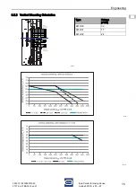
Page 48: ...s Carrier for linking device Series 9419 0 LD1 E1 EN EN EN EN EN EN EN EN EN EN EN EN EN EN EN EN EN EN EN EN EN EN EN EN EN 6 2 Mounting Orientation 6 2 1 Horizontal Mounting Orientation 18018E00 18019E00 18043E00 Type Voltage V DC 9412 00 30 9412 01 17 9412 02 24 ...

Page 49: ...gineering 15 EN EN EN EN EN EN EN EN EN EN EN EN EN EN EN EN EN EN EN EN EN EN EN EN EN Bus Carrier for linking device Series 9419 0 LD1 E1 6 2 2 Vertical Mounting Orientation 18020E 18021E00 1804400 Type Voltage V DC 9412 00 30 9412 01 17 9412 02 24 ...

Page 50: ...ith the fieldbus power supply 9412 refer to the corresponding operating instructions DANGER Explosion hazard due to installation without field enclosure Non compliance results in severe or fatal injuries If used in Zone 2 the device must be installed in an enclosure that meets the requirements of IEC EN 60079 15 DANGER Explosion hazard due to incorrect installation of the device Non compliance res...

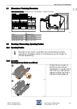
Page 51: ...nsional drawing all dimensions in mm inches Subject to change 18231E00 Operation of bus Carrier is permitted only in the following mounting orientations Installation vertical or horizontal also see the chapter on Project engineering 18027E00 18028E00 Position the bus Carrier on the DIN rail according to IEC EN 60715 Type NS 35 7 5 or NS 35 15 1 and swivel it upwards until the base bolt or both bas...

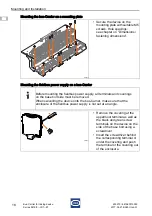
Page 52: ... see chapter on Dimensions fastening dimensions Before mounting the fieldbus power supply all terminals and coverings on the base bolt side must be removed When swivelling the device onto the bus Carrier make sure that the enclosure of the fieldbus power supply is not set at an angle 10859E00 Remove the covering at the uppermost terminal as well as the black and green screw terminals on the device...

Page 53: ...us Carrier 1 Swivel in the device up to the red notch lever Make sure that the red notch lever engages with the cut out of the device 2 Press the red notch lever and device together until you hear the notch lever click into place 18031E00 Position the device at the respective slot and swivel it onto the bus Carrier 1 Swivel in the device up to the red double notch lever Make sure that the red doub...

Page 54: ...e DIN rail The diagnostics communication module DCM is mounted on the mounting position of the bus Carrier to the right of the fieldbus power supplies 18034E00 Start by plugging the ribbon cable into the bus Carrier Use the upper groove to hook the module into the DIN rail profile at the mounting position Swivel the module down until the base bolt engages Carefully plug the ribbon cable into the D...

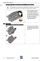
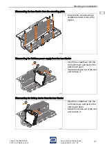
Page 55: ...ounting the fieldbus power supply from the bus Carrier Dismounting the linking device from the bus Carrier 18037E00 Unscrew the screws using a suitable tool and remove the device 18030E00 Insert the screwdriver into the red notch lever and swivel the notch lever open Swivel the device out of the slot and remove it 18032E00 Insert the screwdriver into the red notch lever and swivel the notch lever ...

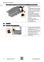
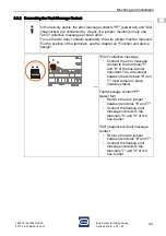
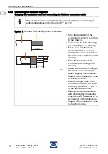
Page 56: ...ector press the unlocking actuators on the side together using two fingers and pull the cable upwards Using a suitable screwdriver disengage the base bolts 1 Swivel the device towards the bus Carrier slightly 2 and then remove it Optionally if desired Pull the ribbon cable off the the bus Carrier as described above 18038E00 Connect the auxiliary power to terminals pri 1 2 optionally redundant red ...

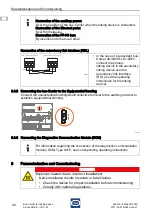
Page 57: ...removed For the position of the terminals see the chapter on Function and device design 18038E00 Error collective message Connect the error message contact to the terminals 5 and 8 of the bus Carrier Important The wire jumper between the terminals 6 and 7 must remain in place delivery status Fault message contact PF power fail Remove the wire jumper between terminals 6 and 7 Connect the floating e...

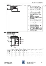
Page 58: ...tion cable 1 according to the drawing Turn down the bare shielding 2 according to the drawing Make sure that the cable diameter with the shielding turned down does not exceed the dimensions indicated on the drawing Strip the insulation of the conductors according to the drawing Make sure that the shielding or the cores are not damaged when stripping the insulation Repeat the procedure for other co...

Page 59: ...rding to the drawing Make sure that the shielding or the cores are not damaged when stripping the insulation Repeat the procedure for other connection cables Connect single cores of the connection cable to the corresponding terminals and S of the fieldbus terminal Repeat the procedure for other connection cables FPS 1 FPS 2 FPS 3 FPS 4 FPS 5 FPS 6 FPS 7 FPS 8 9419 04F LD1 01E1 LD1 S1 LD1 S2 LD1 S3...

Page 60: ...r when the linking device is connected Connection of the Ethernet ports Over RJ45 sleeves Connection of the FF H1 bus By insertion onto the bus Carrier 18086E00 In the case of a redundant bus Carrier 9419 04R LD1 02E1 connect the primary linking device to the secondary linking device over the redundancy link interface RDL see the operating instructions for the linking device For information regard...

Page 61: ...IP switch is in the ON position in this case 18087E00 DANGER Explosion hazard when configuring parameters or switching the DIP switch in Zone 2 Non compliance results in severe or fatal injuries Ensure that the device is de energised before configuring parameters or switching the DIP switch Settings on the DIP switch are permitted at any time in the de energized state or with a hot work permit The...

Page 62: ...them and observing the corresponding commissioning steps see the chapter on Parameterization and commissioning the auxiliary power supply must be switched on 10 2 Indications The corresponding LEDs on the device indicate the operating conditions of the device and the line fault states also refer to chapter Function and Device Design 18040E00 LED Colour Meaning pri LED green Primary auxiliary power...

Page 63: ...the relevant national regulations to determine the type and extent of inspections Adapt inspection intervals to the operating conditions At a minimum check the following points during maintenance work on the device Whether the clamping screws holding the cables are securely seated Whether the device enclosure and or protective enclosure have cracks or other visible signs of damage Whether the perm...

Page 64: ...red Contact customer service personally or Go to the www stahl com website Select Downloads Customer Service RMA Request Fill out the form Wait for confirmation R STAHL s customer service will contact you You will receive an RMA slip after speaking with customer service Send the device along with the RMA slip in the packaging to R STAHL Schaltgeräte GmbH refer to Section 1 1 for the address Observ...

Page 65: ...ents or solvents 13 Disposal Observe national and local regulations and statutory regulation regarding disposal Separate materials when sending it for recycling Ensure environmentally friendly disposal of all components according to the statutory regulations 14 Accessories and Spare Parts NOTICE Malfunction or damage to the device due to the use of non original components Non compliance may lead t...

Page 66: ......

Reviews: