Operation
28
253215 / 941960310090
2017-04-21·BA00·III·en·01
Bus-Carrier for linking device
Series 9419/0..-LD1-..E1
EN
EN
EN
EN
EN
EN
EN
EN
EN
EN
EN
EN
EN
EN
EN
EN
EN
EN
EN
EN
EN
EN
EN
EN
EN
9.1.3 Other Parameterizations
Other parameterizations for:
• FPS Type 9412
• DCM Type 9415
• Linking device FG-200 HSE/FF
See the corresponding operating instructions
10
Operation
10.1 Operation
After locking the electrical lines into place, connecting them and observing the
corresponding commissioning steps (see the chapter on "Parameterization and
commissioning"), the auxiliary power supply must be switched on.
10.2 Indications
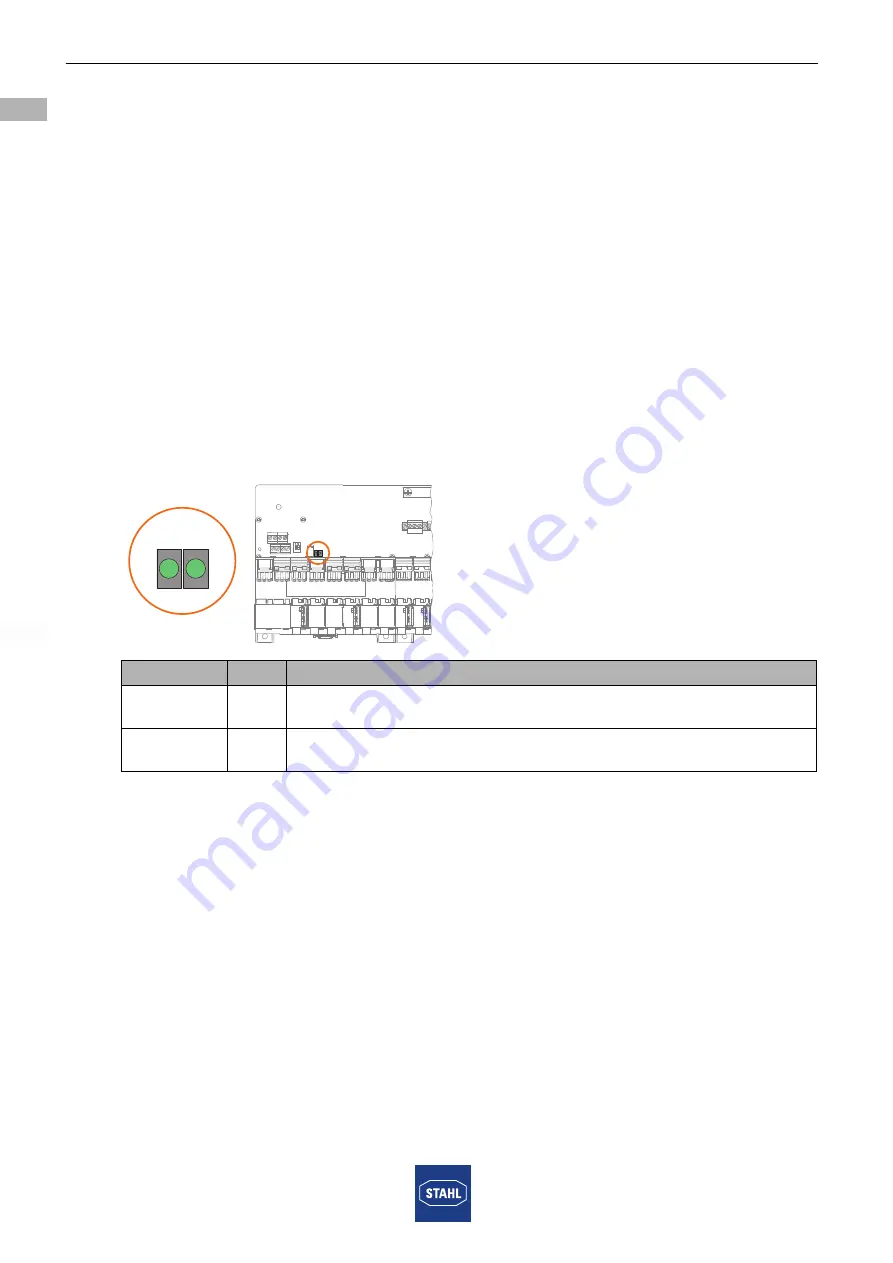
The corresponding LEDs on the device indicate the operating conditions of the device
and the line fault states (also refer to chapter "Function and Device Design").
18040E00
LED
Colour Meaning
"pri" LED
green
Primary auxiliary power connection (the LED lights up only if the
corresponding auxiliary power connection is active).
"red" LED
green
Redundant auxiliary power connection (the LED lights up only if the
corresponding auxiliary power connection is active).
pri
red


