background image

Operating Instructions ET-xx6-A 

Installation 

Page 26 of 60 

 R. STAHL HMI Systems GmbH / OI_ET_xx6_A_en_V_03_00_36.docx / 03.05.2021 

11.2.1 

HMI device Installation in housings type of protection "e" or "t" 

If the HMI devices ET-xx6-A-* are mounted inside a cut out of a suitable housing of protection 
type Ex e or Ex t, its mechanical protection regarding impact and IP code protection up to IP65 is 
maintained even after the device has been installed. The internal separation requirements and 
the  temperature  assessment  of  the  Ex  e  housing  must  be  in  accordance  with  the  applicable 
standards.  The  clearance  of  HMI  device  terminals  to  other  bare  conducting  parts  (excepting 
ground) inside the Ex e housing shall be at least 50 mm [0.16 ft]. 
 

11.2.2 

Cable glands 

The HMI devices of the EAGLE device platform (ET-xx6-A) are factory-fitted with cable glands of 
the type STAHL 8161/* (Ex i - connections) and of the type HSK-M-Ex (Ex e connections). These 
are  selected  so  that  they  comply  with  all  relevant  approvals  for  the  device.  The  Ex-relevant 
markings on the device also contain the bushings and are not necessarily specially marked when 
the device is shipped from the factory. The following must be observed: 

  Unused cable glands must be closed with certified screw plugs or stopping plugs. 

  The tightening torques for the cable glands may vary depending on the cables and wires 

used. The users have to determine and apply the required torques themselves. 

  In the case of ex-factory systems, all components are installed correctly and in accordance 

with  applicable  standards.  Since  storage  or temperature  etc. can  have  an  impact  on  the 
cables and cable glands, the pre-installed screw connections must be checked and possibly 
tightened before commissioning. 

  If  they  are  too  loose  or  too  tight,  the  type  of  protection,  sealing  or  strain  relief  might  be 

negatively impacted. 

  Cable  glands  with  cap  nut  and  without  strain  relief  clamp  should  only  be  used  for 

permanently installed cables and electrical lines. Installation of the required strain relief is 
the responsibility of the system set-up engineer. 

 
Alternative, similar and certified cable glands may be used provided they have an equal or higher 
area of certification (zone) and permitted temperature range, and the same country approval (e.g. 
ATEX for Europe) as the HMI device. 
Open enclosure holes without cable glands are not permitted and must be closed with a certified 
screw plug. This certified screw plug must have an equal or higher area of certification (zone) and 
permitted temperature range, and the same country approval (e.g. ATEX for Europe) as the HMI 
device. 


Summary of Contents for ET-306-A Series

Page 1: ... SERIES 400 Panel PC SERIES 500 Thin Clients HW Rev ET xx6 A FX 03 00 12 HW Rev ET xx6 A TX 03 00 22 HW Rev ET xx6 A FX BT 03 00 16 HW Rev ET xx6 A TX BT 03 00 26 HW Rev ET 3x6 A FX BS 03 00 17 HW Rev ET 3x6 A TX BS 03 00 27 Operating Instructions version 03 00 36 Issue date 03 05 2021 ...

Page 2: ... may be subject to change without notice Any warranty claims are limited to the right to demand amendments Liability for any damage that might result from the content of this description or all other documentation is limited to clear cases of premeditation We reserve the right to change our products and their specifications at any time provided it is in the interest of technical progress The infor...

Page 3: ...information of which particular note should be taken Information highlighted by this symbol refers to a different chapter or section in this manual or other documentation or a web page Warnings Caution In ambient temperatures exceeding 45 C the surface of the devices may heat up Caution when touching Caution The laser diodes installed in our Exicom operator devices media converters and switches em...

Page 4: ... 12 3 2 Additionally for ET 4x6 A Panel PC 12 3 2 1 All devices up to hardware revision 03 00 x2 12 3 2 2 All devices starting from hardware revision 03 00 x4 12 3 2 3 All devices starting from hardware revision 03 00 x6 12 3 3 Additionally for ET 5x6 A Thin Clients 13 3 3 1 All devices up to hardware revision 03 00 x2 13 3 3 2 All devices starting from hardware revision 03 00 x4 13 3 3 3 All devi...

Page 5: ...2 Assembly and disassembly 30 12 1 General information 30 12 2 Cut out ET xx6 A 30 12 3 Assembly free area 31 13 Operation 32 13 1 General information 32 13 2 Connections 32 13 2 1 Dip switch settings S3 and S4 34 13 2 2 Status LEDs 34 13 2 2 1 LEDs 34 13 3 Connection of Readers 36 13 3 1 Type RSi1 connection version 1 36 13 3 2 Type RSi1 connection version 2 36 14 Maintenance service 37 14 1 Dama...

Page 6: ...41 17 3 2 1 Recovery 42 17 3 2 2 Company specific Windows installations 42 17 3 3 Initial start up 42 17 3 4 Recovery Stick 42 17 3 5 Back up 42 17 3 6 Switching off closing down 43 17 3 7 Data loss 43 17 4 Defective pixels 44 17 4 1 Terminology 44 17 4 2 Display specification 45 18 Certification Drawing NEC 46 19 Control Drawing 47 19 1 NEC 47 19 2 CEC 50 20 Declarations of conformity 53 20 1 EC ...

Page 7: ...ry as well as the operating instructions of the additional equipment to be connected Please note that all certificates of the HMI devices can be found in a separate document CE_ET xx6 A You can find this document in the internet at r stahl com or request it from R STAHL HMI Systems GmbH 2 Device function The ET xx6 A HMI devices are explosion proof equipment for installation in hazardous areas and...

Page 8: ...eady to run straight away As a standard all Panel PC s are equipped with a touch screen and several interfaces and are based on the powerful Atom technology making them the most powerful devices on the market 2 6 ET 5x6 A SERIES 500 Thin Clients The ET 5x6 A devices of the 500 SERIES can be integrated into modern networks as Thin Clients or with a KVM box via KVM over IP thus providing ideal and f...

Page 9: ...reen activation Low activation pressure 0 1 up to max 1 N Touchscreen input method Finger gloved finger or stylus Touchscreen durability Polyester foil is easily scratched with high pressure force the spacer dots could be damaged Touchscreen scratch hardness MoHS Touchscreen scratch hardness pencil hardness test ISO 15184 3H Touchscreen transmissivity optics Small milky effect due to the foil Touc...

Page 10: ... Ex e PS 2 Ex ia Seriell COM1 Readers COM2 Audio USB Ex ib 1x USB female connector type A 1x screw terminals 2 5 mm2 AWG14 green Ethernet optical fibre FX SC duplex female connector Data cable lenght Copper TX up to 100 m 330 ft via CAT5 installation cable AWG22 Optical fibre FX up to 2000 m 6562 ft via 62 5 125 μm core external cross section multi mode optical fibre cable Front plate Polyester on...

Page 11: ...ions valid for all devices Level Test specification Relative humidity 90 at 40 C 104 F without condensation Damp heat 55 C 131 F 95 IEC 60068 2 30 2005 55 C 131 F 2 C 35 6 F 95 Location Class for humidity B DNV cyclic 2x 24 h 55 C 131 F 90 100 20 C 68 F 80 100 LR Type Approval TA 02 2002 Corrosion resistant ISA S71 04 1985 severity level G3 EN 60068 2 60 Vibration Vibration sinus 5 up to 13 2 Hz 1...

Page 12: ...ires SPSPlusWIN V 6 Movicon CE 4096 I O 3 1 3 All devices starting from hardware revision 03 00 x7 Type of data memory Flash memory M 2 Solid State Drive SSD internal via SATA 3 2 Additionally for ET 4x6 A Panel PC 3 2 1 All devices up to hardware revision 03 00 x2 Processor Intel Atom N270 1 6 GHz RAM 1 or 2 GB Data memory 4 or 16 GB 128 GB MLC 128 GB SLC Type of data memory Flash memory SATA Ope...

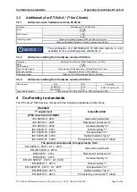
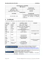
Page 13: ...te Firmware 3 3 3 All devices starting from hardware revision 03 00 x6 Data memory Size TBW Test profile 64 GB MLC 18 75 JESD218 Client profile 128 GB MLC 37 5 Type of data memory Flash memory M 2 Solid State Drive SSD internal via SATA 4 Conformity to standards The ET xx6 A HMI devices comply with the following standards and directives Standard Classification 1st supplement ATEX directive 2014 34...

Page 14: ...x TUR 11 0006X EAC Russia EAЭC RU C DE HA91 B 00085 19 NEC USA UL 20130611 E202379 CEC Canada CSA 2512677 PESO India A P HQ MH 104 5004 P391127 CCE P391127 1 Identification number INMETRO Brazil UL BR 12 0265X KCC Korea Device restriction see notice KGS 12 GA4BO 0215X 12 GA4BO 0317X CCC China 2020312309000285 CNEX CNEx18 5523X RCM Australia According to declaration of conformity DNV GL Marine ship...

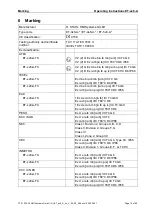
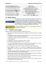
Page 15: ... tb ia ib op is IIIC T80 C Db IP66 EAC ET xx6 A TX 1Ex d e ia ib mb ia ib IIC T4 Gb X Ex ia tb ia ib IIIC T80 C Db ET xx6 A FX 1Ex d e ia ib mb ia ib op is IIC T4 Gb X Ex ia tb ia ib op is IIIC T80 C Db PESO Ex d e ia ib mb ia ib IIC T4 Gb KCC KGS Ex d e ia ib mb ia ib IIC T4 Ex ia tb ia ib IIIC T80 C Db IP66 NEC Class I Division 2 Groups A B C D Class II Division 2 Groups F G Class III Class I Zo...

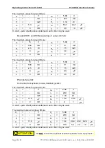
Page 16: ... 5 mm AWG14 may be connected to any of the terminals of the HMI devices When connecting cables to the terminals please make sure that the insulation of the cables goes right up to the terminal contacts 7 1 1 1 Tightening torque For the terminals X1 and X11 a tightening torque of 0 4 Nm up to 0 5 Nm is valid and for the terminals X2 X3 X4 X5 X6 X7 X8 and X9 a tightening torque of 0 5 Nm bis 0 6 Nm ...

Page 17: ...g voltage Um 30 VDC RS 422 232 COM 1 X2 Rated voltage RS 422 5 VDC RS 232 12 VDC Max operating voltage Um 253 VAC USB 1 X5 Rated voltage 5 VDC Max operating voltage Um 253 VAC USB 3 X7 Rated voltage 5 VDC Max operating voltage Um 253 VAC Copper Ethernet X11 Rated voltage 5 VDC Rated power 100 mW Max operating voltage Um 30 VDC Audio X3 Rated voltage 5 VDC Max operating voltage Um 253 VAC 8 2 Exter...

Page 18: ...0 20 10 5 H Co and Lo pairs directly above underneath each other may be used USB 2 X6 The maximum values for group IIC are Ui V Uo 5 9 V Ii mA lo 2 18 A Pi mW Po 1 24 W Ci 0 F Co 5 1 11 28 43 F Li 0 mH Lo 10 5 2 1 H Co and Lo pairs directly above underneath each other may be used The maximum values for group IIB are Ui V Uo 5 9 V Ii mA lo 2 18 A Pi mW Po 1 24 W Ci 0 F Co 14 40 79 200 F Li 0 mH Lo ...

Page 19: ... 10 H Co and Lo pairs directly above underneath each other may be used Reader RSi1 and RSi2 signal input output X8 5 8 The maximum values for group IIC are Ui 15 V Uo 5 36 V Ii 500 mA lo 46 mA Pi 2 5 W Po 62 mW Ci 0 F Co 46 F Li 0 mH Lo 2 H The maximum values for group IIB are Ui 15 V Uo 5 36 V Ii 500 mA lo 46 mA Pi 2 5 W Po 62 mW Ci 0 F Co 79 F Li 0 mH Lo 20 mH Reader WCR1 X8 connection voltage s...

Page 20: ...4 F Li 0 mH Lo 2 H The maximum values for group IIB are Ui 15 V Uo 5 88 V Ii 500 mA lo 51 mA Pi 2 5 W Po 75 mW Ci 0 F Co 63 F Li 0 mH Lo 20 H PS2 interface X9 Connection for keyboard mouse trackball joystick The maximum values for group IIC are Ui V Uo 5 88 V Ii mA lo 200 mA Pi mW Po 1 18 W Ci 17 6 F Co 15 4 25 4 F Li 0 mH Lo 2 1 H Co and Lo pairs directly above underneath each other may be used T...

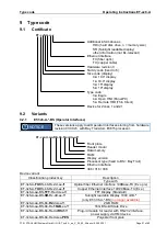
Page 21: ...hardware revision 03 00 x5 with Bay Trail Atom E3815 processor ET xxx A aa BS bb Rx dd ee ff Front plate Reader modul Data memory RAM Display version Processor type fixed to BS Bay Trail Ethernet interface 306 316 336 Device variant Classification product key Description Type with ET 3x6 A FX BS bb Rx dd ee ff Optical fiber Ethernet interface 100Base FX Ex op is ET 3x6 A TX BS bb Rx dd ee ff Coppe...

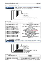
Page 22: ...ight readable display 1000 cd m ET 436 A BT only no longer available ET 4x6 A aa BT Rx bb 64GB dd ee 64 GB Solid State Drive MLC ET 4x6 A aa BT Rx bb 128GBM dd ee 128 GB Solid State Drive MLC ET 4x6 A aa BT Rx bb cc RSi1 ee Plug in module for reader with RS 232 interface power supply via HMI device ET 4x6 A aa BT Rx bb cc dd PES Polyester front plate ET 4x6 A aa BT Rx bb cc dd VA Stainless steel f...

Page 23: ...e device The in each case valid national regulations for installation and assembly apply e g IEC EN 60079 14 The HMI device has been certified as a fixed installed device It must be fixed with a bracket or be secured in another way at a specified position The HMI device must be disconnected from the mains for a change of position The EPL must be adhered to The HMI device must only be switched on w...

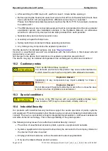
Page 24: ...d and operated in an undamaged dry and clean condition 10 2 Cautionary notes This is an EN 55022 Class A product In a domestic environment this product may cause radio interference in which case the user may be required to take adequate measures Explosion Hazard Substitution of any components may impair suitability for Class I Division 2 Explosion Hazard Do not disconnect Equipment while the circu...

Page 25: ...ng must be connected to the equipotential bonding conductor of the hazardous area The earthing cable s cross section must be at least 4 mm AWG12 and it must be fitted with a suitable cable lug To prevent equalizing currents flowing to the earth ground PE system of the HMI device it is necessary to safely isolate any connected devices from earth or to integrate them into the earth ground PE system ...

Page 26: ... cable glands must be closed with certified screw plugs or stopping plugs The tightening torques for the cable glands may vary depending on the cables and wires used The users have to determine and apply the required torques themselves In the case of ex factory systems all components are installed correctly and in accordance with applicable standards Since storage or temperature etc can have an im...

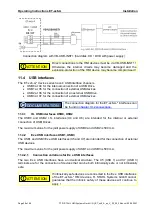
Page 27: ... USB interfaces 11 3 1 Usage of USB Memory Sticks Only USB memory sticks that are certified according to IEC EN 60079 11 may be used In an industrial area a permitted explosion proof memory stick may be connected to the I S USB interface of the HMI device after having been connected to any PC If devices are connected to the I S USB interface that have not been approved by R STAHL HMI Systems GmbH ...

Page 28: ... in chapter 13 2 connections 11 4 1 I S USB interfaces USB0 USB2 The USB0 and USB2 I S interfaces X4 and X6 are intended for the internal or external connection of USBi Drives The maximum value for the joint power supply of USB0 and USB2 is 500 mA 11 4 2 Ex e USB interfaces USB1 USB3 The USB1 and USB3 Ex e USB interfaces X5 and X7 are intended for the connection of external USB devices The maximum...

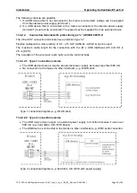
Page 29: ...type e Flexible cables with a cross section of 0 2 2 5 mm AWG24 AWG14 can be used The maximum cable length for the connection with the Ex e USB interfaces X5 and X7 is 2 5 m 8 2 ft The insulation of the wire must reach right up to the terminal body 11 4 2 2 1 Type 1 connection version The USB device does not require an external power supply as it uses less than 500 mA No connection to the mains vi...

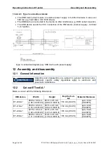
Page 30: ...12 Assembly and disassembly 12 1 General information Assembly and disassembly are subject to general technical rules Additional specific safety regulations apply to electronic and pneumatic installations 12 2 Cut out ET xx6 A Make a cut out with the following dimensions HMI device Width Height Depth of cut out Material thickness ET x06 A 385 5 0 5 mm 1 26 0 0016 ft 257 5 0 5 mm 0 84 0 0016 ft 150 ...

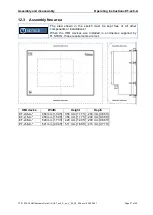
Page 31: ... kept free of all other components or installations When the HMI devices are installed in enclosures supplied by R STAHL these requirements are met HMI device Width Height Depth ET x06 A 484 mm 1 59 ft 356 mm 1 17 ft 200 mm 0 66 ft ET x16 A 458 mm 1 50 ft 356 mm 1 17 ft 200 mm 0 66 ft ET x36 A 526 mm 1 73 ft 426 mm 1 40 ft 200 mm 0 66 ft ET x56 A 621 mm 2 04 ft 511 mm 1 68 ft 215 mm 0 71 ft NOTICE...

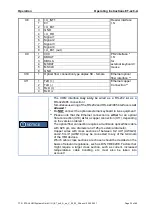
Page 32: ... system at its place of use the cover of the terminal compartment is completely closed 13 2 Connections Terminal Pin Definition Connection X1 1 Power supply HMI device 24 VDC Power supply 2 Power supply HMI device 24 VDC of the 3 Power supply HMI device GND HMI device 4 Power supply HMI device GND X2 1 TxD b B Serial 2 TxD a A COM1 interface 3 RxD b RS 422 485 4 RxD a 5 TxD b 6 TxD a 7 RxD b 8 RxD...

Page 33: ... 232 and RS 422 485 interface is not allowed Do NOT connect the optional external keyboard to live equipment Please note that the Ethernet connection is either for an optical fibre connection X10 or for a copper connection X11 depending on the version ordered The optical fiber connection requires a multimode optical fiber cable with 62 5 µm core diameter and 125 µm external diameter Copper wires w...

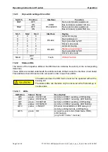
Page 34: ...LEDs at the HMI devices indicates the activity of the corresponding data lines These LEDs are located underneath the additional back lid that covers the interface circuit board This additional back lid needs to be removed in order to see these LEDs In hazardous areas the HMI device must not be operated without the housing lid The status LEDs can therefore only be observed at the first start up or ...

Page 35: ...Operation Operating Instructions ET xx6 A R STAHL HMI Systems GmbH OI_ET_xx6_A_en_V_03_00_36 docx 03 05 2021 Page 35 of 60 Back view of ET xx6 A device LED section at ET xx6 A device ...

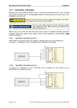
Page 36: ...diagram of each individual reader type please refer to the actual reader documentation or to the Hardware Manual HMI devices of the Panel PC and Thin Client series require an additional software keyboard wedge to transfer the data from the reader into the required application This software is NOT part of the delivery 13 3 1 Type RSi1 connection version 1 With the RSi1 connection version the reader...

Page 37: ...s are tightened fast d All cables and lines are properly connected and undamaged If the device in its factory state is damaged or altered in any way decommission it immediately and contact the manufacturer 14 1 Damaged sealing If the surrounding seal of the device is damaged the manufacturer will tick the No hazloc approved panel mount option on the device The device is only approved for installat...

Page 38: ... been authorized by the manufacturer 16 Disposal Restricted substances Disposal of old electric and electronic devices packaging and used parts is subject to regulations valid in whichever country the device has been installed For countries under the jurisdiction of the EU the corresponding WEEE directive applies The devices are classified according to the table below Directive WEEE II directive 2...

Page 39: ...ective BR2330 Lithium coin cell ATOM boards 3 2 Ethylene glycol dimethyl ether 1 2 Dimethoxyethan EGDME 110 71 4 3 8100 16 1 2 ROHS directive 2011 65 EC The devices meet the requirements of RoHS Directive 2011 65 EU 16 1 3 IMO Resolution MEPC 269 68 The devices meet the requirements of the MEPC 269 68 Resolution of the International Maritime Organization IMO in particular the 2015 Guidelines for t...

Page 40: ...functions and or key bit functions The key pressed second is ignored The key kombination of Ctrl Alt Del can NOT be realized via the virtual keyboard For this you must use an external connected keyboard If you like to have a simulation from the key kombination of Ctrl Alt Del via the F keys of the HMI device it must be stated when ordering as it can only be done by the manufacturer before delivery...

Page 41: ...mes For further information regarding this Write Protection EWF please refer to the OpenHMI_help_en chm help file in the STAHL folder on the device or on the CD DVD USB stick that is included in the delivery 17 3 2 Windows 10 IoT Enterprise 2019 LTSC operating system The operating system is based on Windows 10 for PC platforms with 64 bit x86 processors For the LTSC Long Term Servicing Channel ver...

Page 42: ...re users have to select certain settings Please follow the instructions of the installation assistant 17 3 4 Recovery Stick To restore your Panel PC device to its original state you will need a Recovery Stick which is available as an optional extra This recovery stick USB drive also available intrinsically safe contains the factory image with which the system can be restored to delivery status wit...

Page 43: ...mage of the device may be damaged rendering the HMI device non functioning After the data has been stored Windows informs the user that the HMI device can now be switched off Only switch off the HMI device once you have received this message 17 3 7 Data loss In the case of applications that require constant writing into memory R STAHL HMI systems recommends you use external storage media USB stick...

Page 44: ...n the display consisting of 3 sub pixels in the basic colours red green and blue R G B Dot Sub pixel in the basic colour red green or blue or or Bright Sub pixel dot to which light is passing through creating a bright dot that is on Dark Sub pixel dot to which no light is passing through creating a dark dot that is off adjacent dots dots positioned next to one another horizontally vertically or di...

Page 45: ...efective pixels bright dots 3 2 2 dark dots 4 3 5 total number of dots 5 5 5 adjacent dots 2 bright dots not permitted 1 pair 1 pair more than 3 bright dots not permitted 2 dark dots 1 pair 1 pair 2 pairs more than 3 dark dots not permitted Distance between the dots between 2 bright dots not permitted 15 mm 15 mm between 2 dark dots 5 mm 15 mm 15 mm between 1 bright and 1 dark dot 15 mm 15 mm 15 m...

Page 46: ...Operating Instructions ET xx6 A Certification Drawing NEC Page 46 of 60 R STAHL HMI Systems GmbH OI_ET_xx6_A_en_V_03_00_36 docx 03 05 2021 18 Certification Drawing NEC ...

Page 47: ...Control Drawing Operating Instructions ET xx6 A R STAHL HMI Systems GmbH OI_ET_xx6_A_en_V_03_00_36 docx 03 05 2021 Page 47 of 60 19 Control Drawing 19 1 NEC ...

Page 48: ...Operating Instructions ET xx6 A Control Drawing Page 48 of 60 R STAHL HMI Systems GmbH OI_ET_xx6_A_en_V_03_00_36 docx 03 05 2021 ...

Page 49: ...Control Drawing Operating Instructions ET xx6 A R STAHL HMI Systems GmbH OI_ET_xx6_A_en_V_03_00_36 docx 03 05 2021 Page 49 of 60 ...

Page 50: ...Operating Instructions ET xx6 A Control Drawing Page 50 of 60 R STAHL HMI Systems GmbH OI_ET_xx6_A_en_V_03_00_36 docx 03 05 2021 19 2 CEC ...

Page 51: ...Control Drawing Operating Instructions ET xx6 A R STAHL HMI Systems GmbH OI_ET_xx6_A_en_V_03_00_36 docx 03 05 2021 Page 51 of 60 ...

Page 52: ...Operating Instructions ET xx6 A Control Drawing Page 52 of 60 R STAHL HMI Systems GmbH OI_ET_xx6_A_en_V_03_00_36 docx 03 05 2021 ...

Page 53: ...Declarations of conformity Operating Instructions ET xx6 A R STAHL HMI Systems GmbH OI_ET_xx6_A_en_V_03_00_36 docx 03 05 2021 Page 53 of 60 20 Declarations of conformity 20 1 EC ...

Page 54: ...Operating Instructions ET xx6 A Declarations of conformity Page 54 of 60 R STAHL HMI Systems GmbH OI_ET_xx6_A_en_V_03_00_36 docx 03 05 2021 ...

Page 55: ...Declarations of conformity Operating Instructions ET xx6 A R STAHL HMI Systems GmbH OI_ET_xx6_A_en_V_03_00_36 docx 03 05 2021 Page 55 of 60 20 2 RCM ...

Page 56: ...Operating Instructions ET xx6 A Declarations of conformity Page 56 of 60 R STAHL HMI Systems GmbH OI_ET_xx6_A_en_V_03_00_36 docx 03 05 2021 ...

Page 57: ...Declarations of conformity Operating Instructions ET xx6 A R STAHL HMI Systems GmbH OI_ET_xx6_A_en_V_03_00_36 docx 03 05 2021 Page 57 of 60 20 3 EAC ...

Page 58: ...Operating Instructions ET xx6 A Declarations of conformity Page 58 of 60 R STAHL HMI Systems GmbH OI_ET_xx6_A_en_V_03_00_36 docx 03 05 2021 ...

Page 59: ... Adaption section Marking Removal of type code tables with AMD Geode LX and Atom N270 processor Chapter Cable glands now in list form Addition of section Material declaration Addition of sub section RoHS in section Material declaration Addition of section Industrial Security Addition of section Assembly free area Addition of EAC declaration of conformity Formal changes Version 03 00 36 Addition of...

Page 60: ...olf Grimme Allee 8 D 50829 Köln T Sales Support 49 221 768 06 1000 Technical Support 49 221 768 06 5000 F 49 221 768 06 4100 E Sales Support sales dehm r stahl com Technical Support support dehm r stahl com r stahl com exicom de ...

Reviews: