255118 / 815060300340
2017-04-19·BA00·III·en·01
Product selection, project engineering and modification
13
EN
EN
EN
EN
EN
EN
EN
EN
EN
EN
EN
EN
EN
EN
EN
EN
EN
EN
EN
EN
EN
EN
EN
EN
EN
Terminal box
Series G150/1
5.4
Internal built-in components (terminals)
5.4.1 Ascertain the number of conductors using the table from the EU Type Examination Certificate
Refer to the specifications in the EU Type Examination Certificate for the maximum
permitted number of conductors – in relation to the current load and conductor
cross-section.
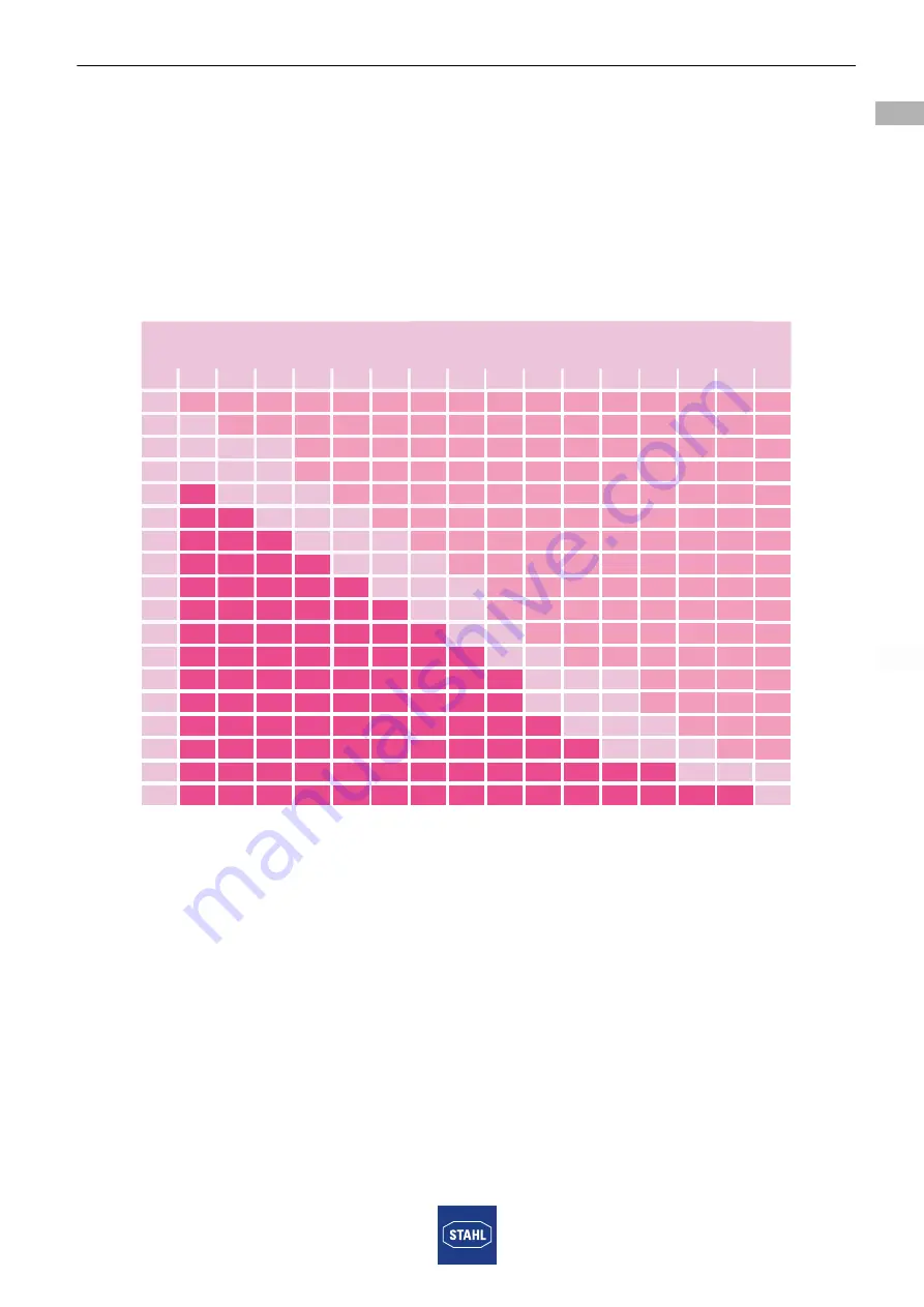
Taking enclosure 8150/1-0250-0180-120 as an example: The maximum permitted number of
conductors can be ascertained using the following table.
12543E00
*) Current, **) conductor cross-section
Explanations of the table:
Each inserted conductor and each internal connection conductor must be selected. Jumpers
and protective conductors are not considered as conductors.
Non-critical (light area of the table)
The light area is non-critical in terms of heating up the enclosure. Circuits classified as being
in this area can be incorporated in the enclosure in any number.
Critical (inscribed area of the table)
The part of the table shows the maximum permissible number of conductors considering the
cross-sections of the conductors and the continuous current loading. When using this table,
simultaneous factors and load factors may be accounted for. Mixed arrangements with
circuits of different cross-sections and currents are possible; in this case the proportion of the
loading from the individual circuits should be taken into account. If a terminal box is fully
loaded according to the criteria in the dark part of the table, then any number of circuits from
the non-critical (light part of the table) may be added.
8150/1-0250-0180-120
[A]*
[mm²]**
1,5
20
16
10
6
25
35
50
63
80
100
125
160
200
225
250
315
400
500
63
21
42
163
9
24
47
11
26
51
7
20
50
3
16
41
5
19
68
7
21
76
9
20
8
20
7
18
56
15
48
2
9
19
4
11
24
2
7
14
3
9
28
5
2,5
4
6
10
16
25
35
35
50
70
95
120
150
185
240
300


