244375 / 815060300270
2015-06-24·BA00·III·en·00
Mounting and installation
7
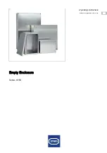
Empty Enclosure
Series G150
EN
EN
EN
EN
EN
EN
EN
EN
EN
EN
EN
EN
EN
EN
EN
EN
EN
EN
EN
EN
EN
EN
EN
EN
EN
7
Mounting and installation
7.1
Dimensions / fastening dimensions
The dimensions can be found in the drawings supplied with the device.
If additional through holes are required, for example for fastening cable glands, breathers
or other built-in parts in the enclosure, the following has to be observed:
• When determining positions of the through holes, observe the mounting distance to
ensure collision-free mounting.
• Space requirements result from the width across corners of the cable gland plus the
space required for the tool used to fasten the cable gland.
• Adjust the hole diameters to the dimensions of the built-in parts and/or their seals.
• Measure the dimensions on the plane surfaces of the inner side of the enclosure,
not on the outer side of the enclosure.
• Make sure that the through holes are located on the plane surfaces of the enclosure
sides with parallel running interior and exterior contours.
• Additional through holes can be bored, laser-cut or punched.
• During punching make sure that the surfaces remain flat.
• Do not damage circumferential sealing lips.
All dimensions in mm - subject to modifications
14282E00
G150/. fastening dimensions
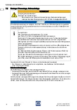
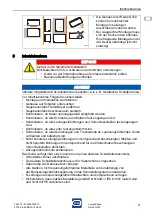
DANGER
Danger due to leaking holes!
Non-compliance results in severe or fatal injuries.
• Seal open holes protected with an adhesive tape by means of adapted
and certified components.
• Remove the adhesive tape completely.
• Make sure that the components comply with the IP-protection.
25
7 [0,28]
18 [0,71]
26 [1,02]
20
X
ø [ø 0,28]
7
[0,98]
[0,79]

