background image

Operating Instructions Scanner IDM 

Marking 

 R. STAHL HMI Systems GmbH / OI_Scanner_IDM_en_V_01_00_04.docx / 29.01.2016 

Page 11 of 36 

Marking 

6.1 

IDM handheld scanner 

Manufacturer 

R. STAHL HMI Systems GmbH 

Type code 

IDM160-ex 
IDM160-PDF-ex 

CE classification: 

c

0158


Testing authority and certificate number: 

IBExU14ATEX1013 

IECEx IBE 14.0003 

Ex classification: 


ATEX guideline 94/9/EC 

II 2 G Ex ib IIC T4 Gb 

II 2 D Ex ib IIIC T135°C Db 


IECEx 


Ex ib IIC T4 Gb 

Ex ib IIIC T135°C Db 


KGS 


Ex ib IIC T4 

Ex ib IIIC T135°C 


6.2 

IDM bluetooth scanner 

Manufacturer 

R. STAHL HMI Systems GmbH 

Type code 

IDM160-BT-ex 
IDM160-BT-PDF-ex 

CE classification: 

c

0158


Testing authority and certificate number: 

IBExU13ATEX1150 

IECEx IBE 14.0002 

Ex classification: 


ATEX guideline 94/9/EC 

II 2 G Ex ib IIC T4 Gb 

II 2 D Ex ib IIIC T135°C Db 


IECEx 


Ex ib IIC T4 Gb 

Ex ib IIIC T135°C Db 


KGS 


Ex ib IIC T4 

Ex ib IIIC T135°C 


Safety data 

7.1 

IDM barcode scanner / base loading station 


U

i

 = 

5.6V 


I

i

480 mA 


P

i

1.25 W 


C

i

46 µF 


L

i

negligible 


Summary of Contents for IDM160

Page 1: ...re provided the contents and meaning of the safety relevant information remain unaltered Operating Instructions IDM160 barcode handheld scanner IDM160 BT barcode bluetooth scanner R STAHL HMI Systems GmbH Adolf Grimme Allee 8 D 50829 Köln Version 01 00 04 Issue date 29 01 2016 ...

Page 2: ... part except with the written consent of the publisher Subject to alterations Any warranty claims are limited to the right to demand amendments Liability for any damage that might result from the contents of these instructions or all other documentation is limited to clear cases of premeditation We reserve the right to change our products and their specifications at any time provided it is in the ...

Page 3: ...sers to hazards that may result in death or serious injury if ignored This sign alerts users to hazards that may damage machinery or equipment or result in injury if ignored Information highlighted by this symbol indicates measures for the prevention of damage to machinery or equipment Information highlighted by this symbol indicates important information of which particular note should be taken I...

Page 4: ... 1 ATEX 10 5 1 2 IECEx 10 5 1 3 KGS 10 5 2 IDM160 BT bluetooth scanner 10 5 2 1 ATEX 10 5 2 2 IECEx 10 5 2 3 KGS 10 6 Marking 11 6 1 IDM handheld scanner 11 6 2 IDM bluetooth scanner 11 7 Safety data 11 7 1 IDM barcode scanner base loading station 11 8 Type code 12 8 1 IDM barcode scanner 12 8 2 Base loading station 12 9 Safety Advice 13 9 1 Installation and operation 13 9 1 1 IDM handheld scanner...

Page 5: ...eaderbox 054 DC RS232 20 11 2 1 6 Connection of Readerbox 054 DC RS232 to ET MT xx6 21 11 2 1 7 Connection of Readerbox 054 DC RS232 to ET MT xx7 23 11 2 2 Connection Readerbox 054 AC RS422 25 11 3 Bluetooth scanner IDM160 BT 28 11 3 1 Battery 28 11 3 2 Base loading station 29 12 Maintenance service 30 12 1 Servicing 30 13 Troubleshooting 30 14 Disposal 30 14 1 ROHS directive 2011 65 EC 30 15 Aces...

Page 6: ...ocument online at www stahl hmi de or request a copy from R STAHL HMI Systems GmbH 2 Function The type IDM barcode scanners are used to capture data and transmit them to PCs and similar devices in hazardous areas They are explosion protected equipment for installation in hazardous areas of zones 1 2 21 and 22 The ReaderBox 054 supply module is used for the scanner s power supply and data communica...

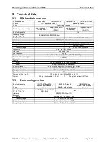
Page 7: ...cy 500 Hz Reader distance 50 800 mm 0 5 mm 0 164 2 63 ft 0 00164 ft Resistance to outside light interference 100 000 lx Signals optical 2x LED operating status read confirmation acoustic Beeper buzzer can be switched off Shock resistance 50 drops from a height of 2 m onto a concrete surface Ambient temperature 20 C to 50 C 4 F to 122 F Storage temperature 30 C to 70 C 22 F to 158 F Type of protect...

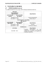
Page 8: ...tion ATEX directive until 19 04 2016 from 20 04 2016 94 9 EC 2014 34 EU EN 60079 0 2012 General requirements EN 60079 11 2012 Intrinsic safety i Electromagnetic compatibility EMC directive until 19 04 2016 from 20 04 2016 Classification 2004 108 EC 2014 30 EU EN 61000 6 2 2006 Immunity EN 61000 6 3 2007 Interference emission RoHS directive 2011 65 EU Classification EN 50581 2012 Technical document...

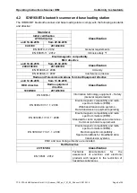
Page 9: ...uipment directive until 12 06 2016 from 13 06 2016 Classification RED directive Radio equipment directive 1999 5 EC 2014 53 EU EN 60950 1 Information technology equipment Safety General requirements EN 300328 V1 7 1 2006 Electromagnetic compatibility and radio spectrum matters ERM Wideband transmission systems Data transmission equipment operating EN 301489 1 V1 8 1 2008 Electromagnetic compatibil...

Page 10: ...TEX The ATEX certificate is listed under the following certification number Certificate number IBExU14ATEX1013 5 1 2 IECEx The readers IECEx certification has the following number Certificate number IECEx IBE 14 0003 5 1 3 KGS The KGS certificate is listed under the following certification number Certificate number 14 KB4BO 0725 and 14 KB4BO 0726 5 2 IDM160 BT bluetooth scanner 5 2 1 ATEX The ATEX...

Page 11: ...4 Gb II 2 D Ex ib IIIC T135 C Db IECEx Ex ib IIC T4 Gb Ex ib IIIC T135 C Db KGS Ex ib IIC T4 Ex ib IIIC T135 C 6 2 IDM bluetooth scanner Manufacturer R STAHL HMI Systems GmbH Type code IDM160 BT ex IDM160 BT PDF ex CE classification c0158 Testing authority and certificate number IBExU13ATEX1150 IECEx IBE 14 0002 Ex classification ATEX guideline 94 9 EC e II 2 G Ex ib IIC T4 Gb II 2 D Ex ib IIIC T1...

Page 12: ...eld scanner with fixed cable two dimensional 2D stacked barcodes PDF417 scannable IDM160 BT ex Scanner Bluetooth one dimensional 1D barcodes scannable IDM160 BT PDF ex Scanner Bluetooth two dimensional 2D stacked barcodes PDF417 scannable 8 2 Base loading station For Bluetooth scanners only Type code IDM160 BT aa bb Explosion protection Digits not present Non Ex Z1 Explosion protected zone 1 Bluet...

Page 13: ...1 base loading station may be installed and operated in zones 1 2 21 and 22 The devices must only be operated when they are fully assembled Users must not open the devices If the enclosure is in any way damaged the device must be removed from the hazardous area immediately The device must be switched off immediately if it is likely that as a consequence of damaging impact or general peculiarities ...

Page 14: ... the devices may not be wiped or cleaned with a dry cloth Ensure safe handling with firm footing and sufficient room for movement Devices fitted with laser fall under standards US 21 CFR 1040 10 and EN 60825 1 The laser s classification is stated on a plate affixed to the device Class 1 lasers are deemed inherently safe during normal use but users must not look directly into the light source The f...

Page 15: ...lth issued by the Government Safety Association and the BetrSichVer Betriebsicherheitsverodnung Occupational Safety and Health Usually all components are installed inside an R STAHL HMI Systems GmbH field enclosure and fully functionally wired unless agreed otherwise R STAHL HMI Systems GmbH eingebaut und vollständig funktionsfähig verdrahtet wenn nichts anderes vereinbart wurde 10 2 Mechanical di...

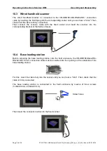
Page 16: ...with the fixed socket and insert the scanner into the corresponding bracket at the field enclosure 10 4 Base loading station Before screwing the base loading station onto the field enclosure the VB IDM160 Base RSi RS232 SR 8m Z1 connection cable must be inserted into the opening on the underside of the base loading station For this insert the cable fully into the socket until you can hear a click ...

Page 17: ... 11 Operation 11 1 General information Before operating the scanners please ensure that all components are complete When operating the devices particular care shall be taken that the devices have been installed according to the directions the devices are not damaged all screws are tightened fast all cables are connected properly ...

Page 18: ...e loading station Readerbox 054 DC RS232 HMI 11 2 1 3 Legend for 11 2 1 1 and 11 2 1 2 Number Description Number Description 1 HMI device ET MT xx6 xx7 7 IDM160 Scanner fixed cable 2 ReaderBox 054 DC RS232 8 IDM160 Scanner Bluetooth 3 Binder fixed socket 9 Base loading station 4 Binder plug 10 VB IDM160 XX6 RS232 SR 5 RS 232 serial interface 11 VB IDM160 Base RSi RS232 SR 8m Z1 6 Voltage connectio...

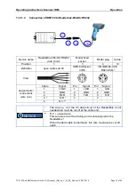
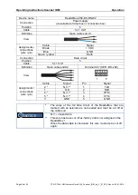
Page 19: ... Definition open cable end X3 IDM160 Socket 3 PE VB IDM160 XX6 RS232 SR View Assignments connections wire pin Cable Signal Pin Signal Pin Signal 1 VDC 1 UB 1 UB 2 GND 2 GND 2 GND 4 RxD 3 TxD 3 TxD 3 TxD 4 4 5 N V The wire no 3 of the X3 data circuit of the ReaderBox is not needed and must be cut off at the cable end N V unused wire This wire was cut off ex factory and is not assigned in the Reader...

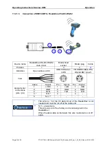
Page 20: ...inition Open cable end X3 IDM160 Socket 3 PE VB IDM160 Base RSi RS232 SR 8m Z1 View Assignments connections wire pin Cable Signal Pin Signal Pin Signal 1 VDC 1 UB 1 UB 2 GND 2 GND 2 GND 4 RxD 3 TxD 3 TxD 3 TxD 4 4 5 N V The wire no 3 of the X3 data circuit of the ReaderBox is not needed and must be cut off at the cable end N V unused wire This wire was cut off ex factory and is not assigned in the...

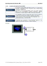
Page 21: ... Connection of Readerbox 054 DC RS232 to ET MT xx6 The 24 VDC voltage supply of the ReaderBox can be connected via the X1 terminals of the ET MT xx6 HMI devices For this make sure you use a power supply of sufficient volume to ensure the total voltage supply of both HMI device and ReaderBox Overview Terminal assignment NOTICE 5 6 5 6 5 6 ...

Page 22: ...D 4 GND Green yellow Earth PA PA connection Equipotential bonding Connection Data circuit Position 5 Cable 5 x 1 mm Definition Open cable endX2 Terminal X2 COM1 RS 232 View 13 9 1 Assignments connections wire pin Cable Signal Pin Signal 2 N V 9 TxD 1 TxD 10 RxD 4 N V 11 RTS 5 N V 12 CTS 3 GND 13 GND The wires of the X2 data circuit of the ReaderBox that are marked with an asterisk are not needed a...

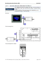
Page 23: ...of Readerbox 054 DC RS232 to ET MT xx7 The ReaderBox cannot be supplied with power via the terminals at the ET MT xx7 HMI units and therefore requires a separate power supply For the connection of the power supply of the ReaderBox use a suitable terminal box or connection box Overview Terminal assignment Terminal assignment in detail NOTICE 5 6 6 5 ...

Page 24: ... GND Green yellow Earth Connection Data circuit Position 5 Cable 5 x 1 mm Definition Open cable endX2 Terminal X97 SER RS 232 View 1 5 Assignments connections wire pin Cable Signal Pin Signal 2 N V 1 TxD 1 TxD 2 RxD 4 N V 3 RTS 5 N V 4 CTS 3 GND 5 GND The wires of the X2 data circuit of the ReaderBox that are marked with an asterisk are not needed and must be cut off at the cable end N V unused wi...

Page 25: ...he actual ReaderBox version see order versions listed in the OI_ReaderBox operating instructions different combinations of power supply and data connections are possible The ReaderBox cannot be supplied with power via the terminals of the HMI units and therefore requires a separate power supply For the connection of the power supply of the ReaderBox use a suitable terminal box or connection box An...

Page 26: ...Operating Instructions Scanner IDM Operation Page 26 of 36 R STAHL HMI Systems GmbH OI_Scanner_IDM_en_V_01_00_04 docx 29 01 2016 Terminal assignment 5 6 ...

Page 27: ...ments connections wire pin Cable Signal Brown L1 Blue N Green yellow Earth Connection Data circuit Position 5 Cable 5 x 1 mm Definition Open cable endX2 Terminal X2 COM1 RS 422 View 13 9 1 Assignments connections wire pin Cable Signal Pin Signal 3 RxD b 1 TxD b 4 RxD a 2 TxD a 1 TxD b 3 RxD b 2 TxD a 4 RxD a 5 Not used Not used unused wire This wire has been cut off ex factory and is not assigned ...

Page 28: ...er screw and remove cover of battery compartment You need to apply a little force to remove the battery compartment s cover Pull out the battery by its lug and insert the replacement battery after having removed its protective cap If the battery has been correctly inserted into the wireless scanner this will be indicated by an acoustic and an optical signal Replace the cover onto the battery compa...

Page 29: ...otected wireless scanner in non hazardous areas two different base loading stations are available see type keys For loading or parking the wireless scanner insert the lower part of the handle into the loading station to ensure that the contacts for loading are connected properly The LED at the head of the scanner will come on to indicate loading The non Ex base loading stations require a power sup...

Page 30: ...lly trained for this purpose Repairs may only be carried out by specially trained staff who are familiar with all basic conditions of the applicable user regulations and if requested have been authorized by the manufacturer 14 Disposal Disposal of packaging and used parts is subject to regulations valid in whichever country the device has been installed The disposal of devices sold after August 13...

Page 31: ...al length of 6 m smooth cable VB IDM160 EXT 4 5m Z1 Extension cable for wired scanner and Binder fixed socket additional length of 4 5 m spiral cable VB IDM160 XX6 USB 1 8m Connection cable for ReaderBox SDVM125 USB and Cable for handheld scanner 1 8 m long VB IDM160 XX6 USB 3 8m as above but 3 8 m long VB IDM160 Base SDVM USB 1 8m Z1 Connection cable for ReaderBox SDVM125 USB and Cable for base s...

Page 32: ...ng Instructions Scanner IDM Declaration of EC conformity Page 32 of 36 R STAHL HMI Systems GmbH OI_Scanner_IDM_en_V_01_00_04 docx 29 01 2016 16 Declaration of EC conformity 16 1 IDM160 barcode handheld scanner ...

Page 33: ...Operating Instructions Scanner IDM Declaration of EC conformity R STAHL HMI Systems GmbH OI_Scanner_IDM_en_V_01_00_04 docx 29 01 2016 Page 33 of 36 16 2 IDM160 BT barcode bluetooth scanner ...

Page 34: ...a circuit X2 Changing of view from cable end at Connection of Readerbox 054 DC RS232 to ET MT xx6 at ReaderBox data circuit X2 Changing of drawing from terminal assignment at Connection of Readerbox 054 DC RS232 to ET MT xx6 Changing of wire colore into wire numbers at Connection of Readerbox 054 DC RS232 to ET MT xx7 at ReaderBox data circuit X2 Changing of view from cable end at Connection of Re...

Page 35: ......
Page 36: ...HMI Systems GmbH Adolf Grimme Allee 8 D 50829 Köln Phone switchboard 49 0 221 76 806 1000 Hotline 5000 Fax 4100 E mail switchboard office stahl hmi de hotline support stahl hmi de www stahl de www stahl hmi de ...

Reviews: